IBM 6400-I10 Operation Guide
IBM 6400-I10 Manual
 |
View all IBM 6400-I10 manuals
Add to My Manuals
Save this manual to your list of manuals |
IBM 6400-I10 manual content summary:
- IBM 6400-I10 | Operation Guide - Page 1
6400 Line Matrix Printers Operator's Guide Cabinet and Pedestal Models Form Number S544-5641-00 ©Copyright IBM Corp., 1998 - IBM 6400-I10 | Operation Guide - Page 2
- IBM 6400-I10 | Operation Guide - Page 3
S544-5641-00 6400 Line Matrix Printers Operator's Guide Cabinet and Pedestal Models - IBM 6400-I10 | Operation Guide - Page 4
supports, ensure that you read the general information under "Notices" on page E-mail to [email protected], or by mail to: IBM PRINTING SYSTEMS COMPANY INFORMATION DEVELOPMENT Users - Documentation related to restricted rights - Use, duplication or disclosure is subject to restrictions set - IBM 6400-I10 | Operation Guide - Page 5
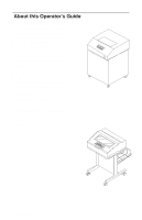
and ribbon, and how to use the optional Power Paper Stacker. Configurations - shows how to use the operator panel to change formatting features. Troubleshooting - gives instructions for clearing paper jams, cleaning the printer, and understanding fault messages. Pedestal Model Operator's Guide i - IBM 6400-I10 | Operation Guide - Page 6
or damage to the printer, follow the directions in this guide, paying attention to all dangers, cautions, and attentions. Danger and caution notices are numbered. These numbers correspond to the translated versions of the notices in the IBM 6400 Line Matrix Printer Safety Information booklet - IBM 6400-I10 | Operation Guide - Page 7
Configurations 58 Deleting Configurations 60 The Power-On Configuration 62 Protecting Custom Sets 64 Printing Configurations 66 Operator Print Tests 68 TROUBLESHOOTING Clearing Paper Jams 72 Cleaning the Printer 75 Solving Printer Problems 79 Status and Fault Messages 81 Operator's Guide - IBM 6400-I10 | Operation Guide - Page 8
product, program, or service that does not infringe any of IBM's intellectual property rights may be used instead of the IBM product. Evaluation and verification of operation in conjunction with other products, except those expressly designated by IBM, is the user's responsibility. Any performance - IBM 6400-I10 | Operation Guide - Page 9
and, if not installed and used in accordance with the instruction manual, may cause harmful interference to radio communications. Operation of this equipment in a residential area is likely to cause harmful interference, in which case the user will be required to correct the interference at his own - IBM 6400-I10 | Operation Guide - Page 10
compatibility. IBM cannot accept fitting of non-IBM option cards. IBM authorized dealers. IBM cannot be responsible for any interference caused by using other than recommended cables and connectors. This product has been tested interference in which case the user may be required to take adequate - IBM 6400-I10 | Operation Guide - Page 11
zu erwarten sind. (Auszug aus dem EMVG vom 9.Nov.92, Para.3, Abs.4) Hinweis: Dieses Genehmigungsverfahren ist von der Deutschen Bundespost noch nicht veröffentlict worden. Operator's Guide vii - IBM 6400-I10 | Operation Guide - Page 12
in design and manufacture. Remember, however, that this product operates under conditions of high electrical potentials and heat generation, both of which are functionally necessary. Trademarks and Service Marks IBM is a trademark of the IBM Corporation in the United States or other countries or - IBM 6400-I10 | Operation Guide - Page 13
: Before powering on the printer ensure the printer is plugged into an appropriate power source. Refer to Chapter 2 of the Setup Guide for information on proper sources. DANGER: Switch off printer power and unplug the printer power cord before cleaning the printer. Operator's Guide ix - IBM 6400-I10 | Operation Guide - Page 14
x Operator's Guide - IBM 6400-I10 | Operation Guide - Page 15
♦ Power Paper Stacker Option 18 ♦ Changing the Paper Exit Location (Pedestal Models Only) 22 ♦ Loading Paper 26 ♦ Reloading Paper 33 ♦ Unloading Paper 41 ♦ Unloading the Power Stacker 43 ♦ Setting Top-of-Form 45 ♦ Replacing the Ribbon 48 ♦ Canceling a Print Job 51 Operator's Guide - IBM 6400-I10 | Operation Guide - Page 16
into an appropriate power source. Refer to Chapter 2 of the Setup Guide for information on proper sources. Push the On ( | ) side of the switch to power on the printer. Push the Off (f) side of the switch to power off the printer. Cabinet Models Off On Pedestal Models 2 Operator's Guide - IBM 6400-I10 | Operation Guide - Page 17
. If there is a fault during the self-test, the Attention indicator lights and a fault message (such as "001 END OF FORMS") appears on the message display. See page 81 for information on fault messages. powering on the printer Power Ready READY Power Attention 001 END OF FORMS Operator's Guide 3 - IBM 6400-I10 | Operation Guide - Page 18
panel keys are described on the following pages. Operator Panel Layout Status Indicators Message Display Power Ready Processing READY Menu Scroll Enter Micro Line Feed Form Feed Start Attention Printer Configuration Scroll Return Micro View Set Top Stop of Form Cancel Eject/ Restore - IBM 6400-I10 | Operation Guide - Page 19
NOT READY. • PROGRAM - Pressing the Menu key places the printer in PROGRAM state and displays the operator menus. PROGRAM state may be either locked or unlocked. When PROGRAM state is unlocked, you may select and save new configuration settings. When PROGRAM state is locked, you may view the current - IBM 6400-I10 | Operation Guide - Page 20
on. • Ready - On when the printer is in READY state, no errors are pending, and the printer is ready to process data. • Processing - Flashes when the printer is receiving data from the host. • Attention - Flashes when a fault condition occurs. Power Ready Processing Attention 6 Operator's Guide - IBM 6400-I10 | Operation Guide - Page 21
in the NOT READY state. (See page 14.) 1) Menu places the printer in PROGRAM state and displays the first-level operator menu (PRINTER CONTROL). To view the menus without changing settings, press Menu from NOT READY state. To change the configuration settings, press Scroll ° + Scroll ± at the same - IBM 6400-I10 | Operation Guide - Page 22
the current configuration parameters. After pressing Stop, press Printer Configuration. When the display message confirms the Printer Configuration key has been activated, press the Start key to print the configuration or the Stop key to exit the function. Printer Configuration 8 Operator's Guide - IBM 6400-I10 | Operation Guide - Page 23
backward through the options in the current level of the operator menu. Scroll ° + Scroll ± In NOT READY state, press Scroll ° + Scroll ± at the same time to switch PROGRAM state between locked and unlocked. When PROGRAM state is locked, no configuration changes can be made. When PROGRAM state is - IBM 6400-I10 | Operation Guide - Page 24
unlocked PROGRAM state, selects a configuration option value. 3) In PROGRAM state, starts and stops a Print Test selected from the Operator Print Tests menu. 4) In the NOT READY state, pressing Stop + Enter performs a soft reset of the printer, which resets the printer to the power on configuration - IBM 6400-I10 | Operation Guide - Page 25
printer top-of-form to the new position. Micro ° This key operates only in NOT READY state. Press Stop to place the printer in the NOT READY state. (See page Micro Micro ± This key operates only in NOT READY state. Press Stop to place the printer in the NOT READY state. (See page 14.) In NOT READY - IBM 6400-I10 | Operation Guide - Page 26
View a second time performs the same function as pressing View a second time and puts the printer in READY state. Pressing Stop instead of pressing View a second time moves the paper back to its original print position and puts the printer in NOT READY state. 12 Line Feed View Operator's Guide - IBM 6400-I10 | Operation Guide - Page 27
down to the print position and setting the emulation to the top-of-form. See the procedure on page 45 for more information. If there is data in the printer buffer (such as after a paper jam), the printer moves to the position where printing stopped. Operator's Guide using the operator panel Form - IBM 6400-I10 | Operation Guide - Page 28
, which is a soft reset, resets the printer to the power on configuration. 5) After pressing View or Eject to move the print position to the tractor area, press Stop to move the paper back to its original print position, and place the printer in the NOT READY state. 14 Start Stop Operator's Guide - IBM 6400-I10 | Operation Guide - Page 29
carefully to avoid canceling a job accidentally. 1) Stops printer tests in progress. 2) Cancels a print job. Operation depends on the printer interface. a. Coax Interface (non-SCS mode)*: The Cancel key is not effective and the "009 INVALID KEY" error message is displayed. note With a Coax Interface - IBM 6400-I10 | Operation Guide - Page 30
its previous position and the printer goes NOT READY. note If you are using this function to tear off forms, you must press Form Feed before using the Eject/Restore function. This will help avoid unloading the paper while it is restored to its original position. 16 Eject/ Restore Operator's Guide - IBM 6400-I10 | Operation Guide - Page 31
operator panel Eject/Restore (Top Exit Tear Mode) Top Exit Tear Mode is selectable only on pedestal models. It is designed to be used in conjunction with the Top Exit Paper Path. This mode facilitates tearing off forms and adjusting the printer to print position. The printer returns to the mode it - IBM 6400-I10 | Operation Guide - Page 32
the printer to the paper stack. This section explains how to set up and use the optional power stacker. Power Paper Stacker Component Locations The following illustration provides component locations for operating the power paper stacker. Paper Throat Pinch Rollers Rear Control Panel Motor Bracket - IBM 6400-I10 | Operation Guide - Page 33
option Setting Up the Power Paper Stacker 1 Power on the printer. 2 Using the rear control panel, press ONLINE to take the printer to the NOT READY state. Press STACKER UP key and wait for the stacker to reach the top of its travel. Paper Advance Stacker Up Stacker Down Operator's Guide 19 - IBM 6400-I10 | Operation Guide - Page 34
desired paper length (5 to 12 inch range). Grasping the paddle shaft, push or pull toward the front or the rear of the printer, setting the desired paper length by aligning indicator notch on the bearing bracket with the paper length indicator. Paddle Shaft Bearing Bracket 20 Operator's Guide - IBM 6400-I10 | Operation Guide - Page 35
Starting the Power Paper Stacker power paper stacker option 1 Follow steps 1 through 22 in the Loading Paper section (see page 26). printer displays, "NOT READY." If a message other than "NOT READY" displays, refer to the "Trouble Shooting" chapter. 5 Press the START key on the operator panel - IBM 6400-I10 | Operation Guide - Page 36
you will be tearing the forms from the printer and using them soon after printing. Forms will not stack when in this mode. Setting Top Paper Exit 1 Press Stop to place the printer in NOT READY state. note If there is paper in the printer, unload the paper (page 41), then continue with step 2 of this - IBM 6400-I10 | Operation Guide - Page 37
Changing the Paper Exit Location 5 Tighten the two hinge adjustment thumbscrews. 6 Slide the paper guide slightly to the left and raise it to its upper position for the top exit. Top Exit Rear Exit 7 Load paper (page 26), feeding the paper out the top paper exit. Operator's Guide 23 - IBM 6400-I10 | Operation Guide - Page 38
place the printer in NOT READY state. note If there is paper in the printer, unload the paper (page 41), then continue with step 2 of this procedure. 2 Open the printer cover. 3 Loosen the two hinge adjustment thumbscrews. 4 Slide the cover forward until it stops. Thumbscrew 24 Operator's Guide - IBM 6400-I10 | Operation Guide - Page 39
Changing the Paper Exit Location 5 Tighten the two hinge adjustment thumbscrews. 6 Place the paper guide in its lower position. Top Exit Rear Exit 7 Load paper (page 26), feeding the paper out the rear paper exit. Operator's Guide 25 - IBM 6400-I10 | Operation Guide - Page 40
state. 2 Open the printer cover. 3 If necessary, unload the current paper (page 41), then continue with step 7 of this procedure. If not, continue with step 4. 4 Raise the forms thickness lever as far as it will go. 5 Open both tractor doors. 6 Press any key on the operator panel except Form Feed - IBM 6400-I10 | Operation Guide - Page 41
7 Slide the two paper supports sideways and position them toward the center of the area between the tractors. 8 On cabinet models: a. Open the cabinet front door. b. Place the paper supply inside the printer, on the floor of the cabinet. c. Align the paper supply with the front label on the floor of - IBM 6400-I10 | Operation Guide - Page 42
loading paper 11 Feed the paper up through the paper slot. 12 On pedestal models: Make sure the paper is inserted between the two wire guides. 13 Hold the paper in place with one hand (to prevent it from slipping down through the paper slot) and pull it through from above - IBM 6400-I10 | Operation Guide - Page 43
the paper scale and lock it. You can also use the paper scale to count columns. Ribbon Path Diagram attention To avoid damage to the printer caused by printing on the platen, always align the edge of the left tractor door with the number "1" on the paper scale. Paper Scale Operator's Guide 29 - IBM 6400-I10 | Operation Guide - Page 44
the form feed holes. Tractor Door 20 Lock the right tractor. Both tractors are now secured. After both tractors are secured, you can use the horizontal adjustment knob to make fine horizontal adjustments to the paper position. Tractor Lock Horizontal Adjustment Knob 30 Operator's Guide - IBM 6400-I10 | Operation Guide - Page 45
note Do not set the forms thickness lever too tightly; excessive friction can cause paper jams, ribbon jams with potential for ribbon damage, smeared ink, or wavy print. NOTE: Thin Paper = single sheet Medium Paper = two-part form Thick Paper = six-part form 22 On pedestal models: Guide the paper - IBM 6400-I10 | Operation Guide - Page 46
in the printer buffer, such as after a paper jam, go to page 45 to set the top-of-form. b. If there is no data in the buffer, continue with step 24 of this procedure. 24 Press Form Feed several times to ensure that the paper feeds properly beyond the tractors, over the lower paper guide, and - IBM 6400-I10 | Operation Guide - Page 47
to line up the first sheet of the new paper supply. This is especially useful when printing forms, such as labels or invoices. 1 Raise the printer cover. Raise the forms thickness lever as far as it will go. Do not open the tractor doors or remove the existing paper. 2 Press any key on the operator - IBM 6400-I10 | Operation Guide - Page 48
existing paper back. 7 Hold the paper to prevent it from slipping down and through the paper slot. Paper Slot note If you are using multi-part paper and it is too thick for the new paper to be loaded over the existing paper, go to step 18. Paper Slot 34 - IBM 6400-I10 | Operation Guide - Page 49
Load the new paper over the existing paper. Ribbon Path Diagram Existing Paper Perforation 11 Open and load the tractors one at a time to prevent the paper from slipping. note Ensure that the top edge of the new paper lines up with the top perforation of the existing paper. Operator's Guide 35 - IBM 6400-I10 | Operation Guide - Page 50
in the supply area. 17 Close the rear cabinet door. NOTE: Thin Paper = single sheet Medium Paper = two-part form Thick Paper = six-part form Perform steps 18 through 36 only if you are unable to load the new paper over the existing paper in step 3. 18 Open both tractor doors. 36 Operator's Guide - IBM 6400-I10 | Operation Guide - Page 51
forms thickness lever as far as it will go. 20 Remove the paper from the tractors. Allow the paper to fall into the paper supply area. 21 Load a new box of paper in the input area. 22 Feed the Cabinet Model Paper Slot Pedestal Model Paper Slot is 8 inches below printer base Operator's Guide 37 - IBM 6400-I10 | Operation Guide - Page 52
of the left tractor. If adjustment is necessary, unlock the left tractor. Slide the tractor until it is directly to the left of the number "1" on the paper scale and lock it. You can also use the paper scale to count columns. Tractor Door Paper Ribbon Path Diagram Paper Scale 38 Operator's Guide - IBM 6400-I10 | Operation Guide - Page 53
the slot in the top cover. reloading paper Paper Support Tractor Lock 30 Press Form Feed several times to ensure the paper feeds properly beyond the tractors and over the lower paper guide. Feed enough paper to ensure the paper stacks correctly. Horizontal Adjustment Knob Operator's Guide 39 - IBM 6400-I10 | Operation Guide - Page 54
to the top-of-form set previously. If there is data in the printer buffer, the paper moves forward to the last print position on the next page. NOTE: Thin Paper = single sheet Medium Paper = two-part form Thick Paper = six-part form 36 Press Start and close the printer cover. 40 Operator's Guide - IBM 6400-I10 | Operation Guide - Page 55
to fall to the back of the printer and into the paper stacking area. 3 Raise the forms thickness lever as far as it will go. 4 Open both tractor doors. 5 Press any key on the operator panel except Form Feed to silence the alarm. Perforation Tractor Door Operator's Guide Forms Thickness Lever 41 - IBM 6400-I10 | Operation Guide - Page 56
from the cabinet floor. Close the cabinet front door and the printer cover. 11 On pedestal models: Remove the paper supply from the floor or shelf in front of the printer and close the printer cover. Tractor Ribbon Path Diagram Cabinet Models Cabinet Front Door Pedestal Models 42 Operator's Guide - IBM 6400-I10 | Operation Guide - Page 57
the Printer: 1 Unload paper from the print mechanism. See page 41. 2 Open the rear cabinet door. 3 Using the rear control panel, press STACKER UP and wait for the stacker to reach the top of its travel. 4 Remove the paper from the rear of the printer. 5 Close the rear cabinet door. Operator's Guide - IBM 6400-I10 | Operation Guide - Page 58
the tractors and let the paper fall through the power stacker throat. 6 From the rear of the printer, making sure the paper lies with its natural folds, lay the paper on top of the paper stack. 7 Remove the paper from the rear of the printer. 8 Close the rear cabinet door and the cover. 44 Operator - IBM 6400-I10 | Operation Guide - Page 59
top-of-form setting determines where the first line of print appears on a page. 1 If the printer is in READY state, press Stop to place the printer in NOT READY state. 2 Open the printer cover. 3 Raise the forms thickness lever as far as it will go. 4 Press any key on the operator panel except Form - IBM 6400-I10 | Operation Guide - Page 60
you have not yet sent a print job to the printer), the paper moves down NOTE: Thin Paper = single sheet Medium Paper = two-part form Thick Paper = six-part form to the top-of-form position. To verify the top-of-form setting, run one of the operator print tests. See page 68. Check the placement of - IBM 6400-I10 | Operation Guide - Page 61
door. 12 On pedestal models: When printing, ensure that the paper folds the same way in the stacking area as it does in the supply area. Paper will stack only when using the rear exit path. Paper can not be stacked when using the top exit paper path. setting topĆofĆform Operator's Guide 47 - IBM 6400-I10 | Operation Guide - Page 62
Ribbon For detailed ribbon information, refer to your Setup Guide. When replacing ribbons, use only the ribbons listed below: • IBM General Purpose Ribbon, 60yd, P/N 1040990 • IBM General Purpose Ribbon, 100 yd, P/N 1040995 • IBM High Contrast Ribbon, 60 yd, P/N 1040993 • IBM High Contrast Ribbon - IBM 6400-I10 | Operation Guide - Page 63
to the ribbon path diagram on the shuttle cover. Be sure to thread the ribbon between the hammer bank cover and the ribbon mask. attention The ribbon must not be twisted. A twisted ribbon can lower print quality, shorten ribbon life, or cause paper jams. Operator's Guide replacing the ribbon 49 - IBM 6400-I10 | Operation Guide - Page 64
Hammer Bank Cover Hub Latch Ribbon Mask note Do not set the forms thickness lever too tightly; excessive friction can cause paper jams and ribbon jams with potential for ribbon damage, smeared ink, or wavy print. 7 On pedestal models: Lower the operator panel. 8 Close the printer cover. 9 Press - IBM 6400-I10 | Operation Guide - Page 65
your system administrator for additional information. note The Cancel key is not active during View and Eject/Restore operations. To cancel a print job, choose one of the following steps: • For printers using a coax interface, in non-SCS mode*: The Cancel key is not active. Use the host system to - IBM 6400-I10 | Operation Guide - Page 66
the printer returns to READY state. c. Press Cancel. (When pressed, "069 DATA CLEARED" is displayed.) d. Set the top-of-form as described on page 45. *To cancel a print job with the Multi-Platform Interface Coax/Twinax feature, see the Coax/Twinax Multi-Platform Interface Feature Operation Guide. 52 - IBM 6400-I10 | Operation Guide - Page 67
CONFIGURATIONS ♦ Parameters and Configurations 54 ♦ Saving Configurations 56 ♦ Recalling Configurations 58 ♦ Deleting Configurations 60 ♦ The Power-On Configuration 62 ♦ Protecting Custom Sets 64 ♦ Printing Configurations 66 ♦ Operator Print Tests 68 Operator's Guide 53 - IBM 6400-I10 | Operation Guide - Page 68
Printer parameters are settings such as lines per inch (lpi), characters per inch (cpi), and typeface. A configuration is a group of parameters. For example: • 8 lpi • 10 cpi • Data processing typeface, etc. Changing Parameters You can change a parameter by pressing keys on the operator - IBM 6400-I10 | Operation Guide - Page 69
or overwrite any of these eight custom sets. You can also modify the eight configurations and overwrite old parameters. The following pages describe how to perform these functions. To change individual parameters, such as line spacing or typeface, refer to your Setup Guide. Operator's Guide 55 - IBM 6400-I10 | Operation Guide - Page 70
Configurations You can save custom sets by following these procedures. Custom sets are permanently stored and will not be lost if you power off the printer. 1 Press Stop to place the printer in the NOT READY state. NOT READY 2 Press Scroll ° + Scroll ± to unlock the PROGRAM state. OPERATOR MENU - IBM 6400-I10 | Operation Guide - Page 71
your configuration. 9 Press Enter to select the custom set. An asterisk (*) appears next to the selected set in the display. SAVE CURRENT VALUES CUSTOM SET 2* 10 Press Scroll ° + Scroll ± to lock the PROGRAM state. OPERATOR MENU LOCKED 11 Press Start to exit the menu and place the printer in - IBM 6400-I10 | Operation Guide - Page 72
page 56 to save configurations. The following example loads Custom Set 1. 1 Press Stop to place the printer in the NOT READY state. NOT READY 2 Press Scroll ° + Scroll ± to unlock the PROGRAM state. OPERATOR MENU UNLOCKED 3 Press Menu to access the OPERATOR MENU. OPERATOR MENU PRINTER CONTROL - IBM 6400-I10 | Operation Guide - Page 73
. This selects the displayed custom set. LOADING SAVED CONFIGURATION RECALL CUSTOM SET CUSTOM SET 1* 9 Press Scroll ° + Scroll ± to lock the PROGRAM state. OPERATOR MENU LOCKED RECALL CUSTOM SET CUSTOM SET 1* 10 Press Start to return the printer to the READY state. READY Operator's Guide 59 - IBM 6400-I10 | Operation Guide - Page 74
PROGRAM state. OPERATOR MENU UNLOCKED 3 Press Menu to access the OPERATOR MENU. OPERATOR MENU PRINTER CONTROL 4 Press Scroll ° until you reach CONFIGURATION MANAGEMENT. OPERATOR MENU CONFIGURATION MANAGEMENT 5 Press Enter to enter this menu. 6 Press Scroll ° to reach DELETE CUSTOM SET. 7 Press - IBM 6400-I10 | Operation Guide - Page 75
CONFIGURATION DELETE CUSTOM SET 3* 10 Press Scroll ° + Scroll ± to lock the PROGRAM state. OPERATOR MENU LOCKED DELETE CUSTOM SET 3* 11 Press Start to return the printer to the READY state. READY note If the custom set you choose to delete has not previously been saved, the following error - IBM 6400-I10 | Operation Guide - Page 76
on configuration, not the last saved custom set. For your convenience, you can specify which custom set should be the power-on set. 1 Press Stop to place the printer in the NOT READY state. NOT READY 2 Press Scroll ° + Scroll ± to unlock the PROGRAM state. OPERATOR MENU UNLOCKED 3 Press Menu to - IBM 6400-I10 | Operation Guide - Page 77
Set. An asterisk (*) appears next to the selected set in the display. CHANGE POWER ON SET CUSTOM SET 4* 10 Press Scroll ° + Scroll ± to lock the PROGRAM state. OPERATOR MENU LOCKED 11 Press Start to return the printer to the READY state. CHANGE POWER ON SET CUSTOM SET 4* READY Operator's Guide - IBM 6400-I10 | Operation Guide - Page 78
. OPERATOR MENU UNLOCKED 3 Press Menu to access the OPERATOR MENU. OPERATOR MENU PRINTER CONTROL 4 Press Scroll ° until you reach CONFIGURATION MANAGEMENT. OPERATOR MENU CONFIGURATION MANAGEMENT 5 Press Enter to enter this menu. 6 Press Scroll ° until you reach PROTECT CUSTOM SETS. 7 Press - IBM 6400-I10 | Operation Guide - Page 79
appears next to the word ENABLE. PROTECT CUSTOM SETS ENABLE PROTECT CUSTOM SETS ENABLE* 10 Press Scroll ° + Scroll ± to lock the PROGRAM state. OPERATOR MENU LOCKED 11 Press Start to exit the menu and place the printer in the READY state. PROTECT CUSTOM SETS ENABLE* READY Operator's Guide 65 - IBM 6400-I10 | Operation Guide - Page 80
state. OPERATOR MENU UNLOCKED 3 Press Menu to access the OPERATOR MENU. OPERATOR MENU PRINTER CONTROL 4 Press Scroll ° until you reach CONFIGURATION MANAGEMENT. 5 Press Enter to enter this menu. 6 Press Scroll ° repeatedly until you reach the PRINT CUSTOM SET VALUES parameter. 66 OPERATOR MENU - IBM 6400-I10 | Operation Guide - Page 81
CUSTOM SET VALUES CUSTOM SET 6* 10 Your configuration is printed. The printer returns to the NOT READY state. NOT READY 11 Press Scroll ° + Scroll ± to lock the PROGRAM state. OPERATOR MENU LOCKED 12 Press Start to exit the menu and place the printer in the READY state. READY Operator's Guide - IBM 6400-I10 | Operation Guide - Page 82
the Ethernet Interface, you may also print a test page. In the following procedure, printing the error log is shown as an example. 1 Press Stop to place the printer in the NOT READY state. NOT READY 2 Press Scroll ° + Scroll ± to unlock the PROGRAM state. OPERATOR MENU UNLOCKED 3 Press Menu to - IBM 6400-I10 | Operation Guide - Page 83
test runs. To halt the test, press Enter again. Additional tests can be run by returning to step 6. OPERATOR PRINT TESTS PRINT ERROR LOG* 8 Press Scroll ° + Scroll ± to lock the PROGRAM state. OPERATOR MENU LOCKED 9 Press Start to place the printer in the READY state. READY Operator's Guide - IBM 6400-I10 | Operation Guide - Page 84
70 Operator's Guide - IBM 6400-I10 | Operation Guide - Page 85
TROUBLESHOOTING ♦ Clearing Paper Jams 72 ♦ Cleaning the Printer 75 ♦ Solving Printer Problems 79 ♦ Status and Fault Messages 81 Operator's Guide 71 - IBM 6400-I10 | Operation Guide - Page 86
cause the paper to move. The top-of-form setting will be lost. 3 Open both tractor doors. 4 Inspect the paper path and tractors for jammed or torn paper. Remove any pieces of paper by turning the vertical position knob. Forms Thickness Lever Tractor Door Vertical Position Knob 72 Operator's Guide - IBM 6400-I10 | Operation Guide - Page 87
an IBM service representative. 6 Check the paper path between the face of the platen and the ribbon mask for pieces of torn paper and ribbon lint. Refer to the ribbon path diagram on the shuttle cover. Tractor 7 Reload the paper in the tractors. 8 Lower the forms thickness lever. Set it to - IBM 6400-I10 | Operation Guide - Page 88
jams 9 Press Stop to clear the fault message from the message display. 10 Set the top-of-form (page 45). 11 Close the printer cover. 12 Press Start. 13 On cabinet models: a. Open the rear cabinet door. b. Ensure that the paper folds the same way in the stacking area as it does in the supply - IBM 6400-I10 | Operation Guide - Page 89
Periodic cleaning ensures efficient operation and good print quality. DANGER: Switch off printer power and unplug the printer power cord before cleaning the printer. Cabinet Models Cleaning the Outside of the Printer Clean the outside of the printer with a soft, lint-free cloth and mild - IBM 6400-I10 | Operation Guide - Page 90
for particles of paper and ink to accumulate inside the printer. Paper dust and ink buildup must be removed periodically to avoid degraded print quality. 1 Power off the printer and unplug the power cord. 2 Unload the paper supply (page 41). 3 Remove the ribbon (page 48). 76 Operator's Guide - IBM 6400-I10 | Operation Guide - Page 91
. 4 Using a soft-bristled, non-metallic brush, remove dust particles from the paper path, ribbon guides, and ribbon path. Refer to the ribbon path diagram on the shuttle cover. Cabinet Models Splined Shaft Paper Support (2) Tractor 5 Brush and vacuum accumulated dust or residue, especially in the - IBM 6400-I10 | Operation Guide - Page 92
cabinet interior with a clean, lint-free cloth dampened with water and mild detergent. Dry the cabinet interior with a dry, clean, lint-free cloth. 8 Install the ribbon (page 49), load the paper (page 26), and set the top-of-form (page 45). Interior of Lower Cabinet 78 Operator's Guide - IBM 6400-I10 | Operation Guide - Page 93
corrective action task is listed, test the printer after each task. If the problem persists, contact an IBM service representative. Problem Poor print quality: dark print light print light print on half the page missing dots or characters smeared print wavy vertical lines Torn or damaged forms Loss - IBM 6400-I10 | Operation Guide - Page 94
contact an IBM Service Representative. 1 Press Stop to place the printer in the NOT READY state. Press Scroll ° + Scroll ± at the same time to unlock the program state. The message "OPERATOR MENU UNLOCKED" will appear briefly. Press Menu to access the OPERATOR MENU. Display the configuration option - IBM 6400-I10 | Operation Guide - Page 95
more serious faults, however, call an IBM service representative. Fault Ranking The message display shows only one error at a time. If multiple errors occur, the errors are prioritized to determine which error is displayed. After one error is fixed, the next error is displayed. Operator's Guide 81 - IBM 6400-I10 | Operation Guide - Page 96
, turn off power to the printer, then call an IBM service representative. Otherwise, no further attention is required. The following pages list each printer status message and fault message. For fault messages, suggestions are offered for correcting the fault condition. 82 Operator's Guide - IBM 6400-I10 | Operation Guide - Page 97
to put printer in READY state. 009 INVALID KEY PRESS Appears briefly if an inactive key is pressed in current print mode. Re-enter the value, or press the correct key. 010 PARAMETER ERROR Illegal parameter value received in command code. Contact your system administrator. Operator's Guide 83 - IBM 6400-I10 | Operation Guide - Page 98
; host action is required. Paper is jammed in the power stacker area. Remove paper. Power stacker is full of paper. Remove paper. Stacker is not functioning correctly. Check for obstructions in the stacker area. If the problem persists, contact an IBM service representative. 84 Operator's Guide - IBM 6400-I10 | Operation Guide - Page 99
hardware failure. Contact an IBM service representative. A timeout message is sent to the host if paper is not loaded 10 minutes after Stop was pressed to clear the paper out fault. The Intervention Required parameter is set to Send to Host. Load paper. See page 26 for procedure. Operator's Guide - IBM 6400-I10 | Operation Guide - Page 100
set does not exist. Define and save it. (Refer to the Setup Guide.) Custom set is write-protected. Delete existing set, then save new set. (Refer to the Setup Guide.) 044 EC FIRMWARE/HARDWARE ERROR Fatal firmware error on the controller board. Contact an IBM service representative. 86 Operator - IBM 6400-I10 | Operation Guide - Page 101
COIL OPEN 057 CLOSE PLATEN 058 SHUTTLE JAM 059 CANCEL PRINT ACTIVE 060 PRINTER HOT 062 EXHAUST FAN FAULT status and fault messages Controller self-test and initialization sequence were halted at , where is one of 10 numerically coded messages. Contact an IBM service representative - IBM 6400-I10 | Operation Guide - Page 102
on the power supply board. Contact an IBM service representative. Internal power failure. Contact an IBM service representative. Sensors cannot detect current in fan circuit. Refer to the Setup Guide for correction procedure. Internal power failure. Contact an IBM service representative. Controller - IBM 6400-I10 | Operation Guide - Page 103
5V 089 RIBBON STALL CHECK RIBBON 090 SHUTTLE COVER OPEN CLOSE SHUTTLE COVER 092 RIBBON DRIVER CIRCUIT 101 UPPER DRIVER SHORT 102 LOWER DRIVER SHORT 107 HAMMER COIL HOT 110 STACK OVERFLOW SEE USER'S GUIDE status and fault messages Controller voltage failure. Contact an IBM service representative. No - IBM 6400-I10 | Operation Guide - Page 104
SEE USER'S GUIDE Fatal firmware error on the controller board. Contact an IBM service representative. 112 UNDEFINED OPCODE SEE USER'S GUIDE Fatal firmware error on the controller board. Contact an IBM service representative. 113 PROTECTED INSTRUCTION SEE USER'S GUIDE Fatal firmware error on - IBM 6400-I10 | Operation Guide - Page 105
IBM service representative. Fatal firmware error on the controller board. Contact an IBM service representative. Fatal firmware error on the controller board. Contact an IBM service representative. Fatal firmware error on the controller board. Contact an IBM service representative. Operator's Guide - IBM 6400-I10 | Operation Guide - Page 106
FEED PARTLY ENERGIZED SEE USER'S GUIDE Fatal firmware error on the controller board. Contact an IBM service representative. 131 PAPER FEED INTERRUPT SEE USER'S GUIDE Fatal firmware error on the controller board. Contact an IBM service representative. 132 RIBBON INVALID COMMAND SEE USER'S GUIDE - IBM 6400-I10 | Operation Guide - Page 107
and fault messages 137 SHUTTLE INVALID COMMAND SEE USER'S GUIDE 138 SHUTTLE INVALID PARAMETER SEE USER'S GUIDE 139 SHUTTLE OVERSPEED SEE USER'S GUIDE 990 MACHINE CHECK Fatal firmware error on the controller board. Contact an IBM service representative. Fatal firmware error on the controller board - IBM 6400-I10 | Operation Guide - Page 108
coils are indicated. Contact an IBM service representative. Printer state message: printer is offline, not in communication with host. No action necessary. Status message. No action necessary. Status message. No action necessary. OPERATOR MENU UNLOCKED PA1 SELECTED PA2 SELECTED P05 DIAGNOSTIC TEST - IBM 6400-I10 | Operation Guide - Page 109
PLEASE WAIT... RESET IN PROGRESS READY RIBBON INK OUT CHANGE RIBBON SERVICE MENU TESTING HARDWARE PLEASE WAIT TOP OF FORM SET status and fault messages Printer reset in progress. No action necessary. Printer state message: printer is online and in communication with host. No - IBM 6400-I10 | Operation Guide - Page 110
96 Operator's Guide - IBM 6400-I10 | Operation Guide - Page 111
- IBM 6400-I10 | Operation Guide - Page 112
Part Number: 24H8766 S544-5641-00 24H8766
-
 1
1 -
 2
2 -
 3
3 -
 4
4 -
 5
5 -
 6
6 -
 7
7 -
8
-
9
-
10
-
11
-
12
-
13
-
14
-
15
-
16
-
17
-
18
-
19
-
20
-
21
-
22
-
23
-
24
-
25
-
26
-
27
-
28
-
29
-
30
-
31
-
32
-
33
-
34
-
35
-
36
-
37
-
38
-
39
-
40
-
41
-
42
-
43
-
44
-
45
-
46
-
47
-
48
-
49
-
50
-
51
-
52
-
53
-
54
-
55
-
56
-
57
-
58
-
59
-
60
-
61
-
62
-
63
-
64
-
65
-
66
-
67
-
68
-
69
-
70
-
71
-
72
-
73
-
74
-
75
-
76
-
77
-
78
-
79
-
80
-
81
-
82
-
83
-
84
-
85
-
86
-
87
-
88
-
89
-
90
-
91
-
92
-
93
-
94
-
95
-
96
-
97
-
98
-
99
-
100
-
101
-
102
-
103
-
104
-
105
-
106
-
107
-
108
-
109
-
110
-
111
-
112
 |
 |

6400 Line Matrix Printers
Operator's Guide
Cabinet and Pedestal Models
Form Number S544–5641–00
©
Copyright IBM Corp., 1998