IBM 884872U User Guide - Page 20
Server, controls, power, Front
 |
UPC - 000435494092
View all IBM 884872U manuals
Add to My Manuals
Save this manual to your list of manuals |
Page 20 highlights
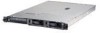
v Predictive Failure Analysis® (PFA) feature on hard disk drives v Read-only memory (ROM) checksums v Remote system problem-analysis support v Status LEDs on the system board v System error logging v Upgradeable BIOS code and baseboard management controller firmware v Vital product data (VPD), including serial-number information and replacement part numbers, stored in complementary metal oxide semiconductor (CMOS) memory, for easier remote maintenance v Wake on LAN capability Server controls, LEDs, and power This section describes the controls and light-emitting diodes (LEDs) and how to turn the server on and off. Front view The following illustration shows the controls, LEDs, and connectors on the front of the server. CD-eject button CD-ROM drive activity LED Hard disk drive activity LEDs Power-on LED Hard disk drive status LEDs USB connectors Operator information panel Power-control button Reset button CD-ROM drive activity LED: When this LED is lit, it indicates that the CD-ROM drive is in use. CD-eject button: Press this button to release a CD from the CD-ROM drive. Hard disk drive activity LEDs: When one of these LEDs is flashing, it indicates that the associated SCSI hard disk drive is in use. Power-on LED: When this LED is lit and not flashing, it indicates that the server is turned on. When this LED is flashing, it indicates that the server is turned off and still connected to an ac power source. When this LED is off, it indicates that ac power is not present, or the power supply or the LED itself has failed. A power-on LED is also on the rear of the server. Note: If this LED is off, it does not mean that there is no electrical power in the server. The LED might be burned out. To remove all electrical power from the server, you must disconnect the power cord from the electrical outlet. Power-control button: Press this button to turn the server on and off manually. Reset button: Press this button to reset the server and run the power-on self-test (POST). You might have to use a pen or the end of a straightened paper clip to press the button. 6 326 Type 8848: User's Guide
-
 1
1 -
2
-
3
-
4
-
5
-
6
-
7
-
8
-
9
-
10
-
11
-
12
-
13
-
14
-
 15
15 -
 16
16 -
 17
17 -
 18
18 -
 19
19 -
 20
20 -
 21
21 -
 22
22 -
 23
23 -
 24
24 -
 25
25 -
26
-
27
-
28
-
29
-
30
-
31
-
32
-
33
-
34
-
35
-
36
-
37
-
38
-
39
-
40
-
41
-
42
-
43
-
44
-
45
-
46
-
47
-
48
-
49
-
50
-
51
-
52
-
53
-
54
 |
 |
