IBM 884872U User Guide - Page 21
Operator, information, panel, drive, activity, System-locator, Information, System-error, connectors
 |
UPC - 000435494092
View all IBM 884872U manuals
Add to My Manuals
Save this manual to your list of manuals |
Page 21 highlights
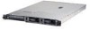
Operator information panel: This panel contains LEDs. The following illustration shows the LEDs on the operator information panel. Hard disk drive activity LED Systemlocator LED Information LED Systemerror LED The following LEDs are on the operator information panel: v Hard disk drive activity LED: When this LED is lit, it indicates that either of the hard disk drives is in use. v System-locator LED: Use this blue LED to visually locate the server if it is in a location with numerous other servers. If your server supports IBM Director, you can use IBM Director to light this LED remotely. v Information LED: When this LED is lit, it indicates that a noncritical event has occurred and is recorded in the error log. An LED near the failing component on the system board is also lit to help isolate the error. v System-error LED: When this LED is lit, it indicates that a system error has occurred. A system-error LED is also on the rear of the server. An LED near the failing component on the system board is also lit to help isolate the error. USB connectors: Connect USB devices to these connectors. Notes: 1. If you want to attach a keyboard or mouse to this server, you must use a USB keyboard or a USB mouse. After installing a USB keyboard, you might need to use the Configuration/Setup Utility program to enable keyboardless operation and prevent POST error message 301 from being displayed during startup. For detailed information about the USB keyboard and how to connect it to your server, see the documentation that comes with the USB keyboard. For information about the Configuration/Setup Utility program, see Chapter 2, "Configuring the server," on page 11. 2. You must use an external USB diskette drive if: v You want to attach a diskette drive to this server. v You need to create an update diskette that contains the latest baseboard management controller firmware (see "Using the baseboard management controller firmware update program" on page 22). v You need to create update diskettes that contain the latest server BIOS code (see "Updating the BIOS code" on page 17). Hard disk drive status LEDs: On some server models, each hot-swap hard disk drive has a status LED. If the status LED for a drive is lit continuously, that individual drive is faulty. The interpretation of a flashing status LED depends on the SCSI controller that is connected to the hot-swap drive, as follows: v When the drive is connected to the integrated SCSI controller with RAID capabilities, a flashing status LED indicates that the drive is a secondary drive in a mirrored pair and the drive is being synchronized. Chapter 1. Introducing the 326 Type 8848 server 7 Eserver
-
 1
1 -
2
-
3
-
4
-
5
-
6
-
7
-
8
-
9
-
10
-
11
-
12
-
13
-
14
-
15
-
 16
16 -
 17
17 -
 18
18 -
 19
19 -
 20
20 -
 21
21 -
 22
22 -
 23
23 -
 24
24 -
 25
25 -
 26
26 -
27
-
28
-
29
-
30
-
31
-
32
-
33
-
34
-
35
-
36
-
37
-
38
-
39
-
40
-
41
-
42
-
43
-
44
-
45
-
46
-
47
-
48
-
49
-
50
-
51
-
52
-
53
-
54
 |
 |
