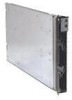
IBM HS21 User Guide - Page 45
Installing, expansion - memory slots
 |
UPC - 000435947550
View all IBM HS21 manuals
Add to My Manuals
Save this manual to your list of manuals |
Page 45 highlights
7. Orient the expansion-card and slide the slots at the back end of the card onto the pins on the expansion card standoff; then, gently pivot the card into the blade-expansion connector. 8. Firmly press on the indicated locations to seat the expansion card. Note: For device-driver and configuration information to complete the installation of the expansion card, see the documentation that comes with the expansion card. 9. If you have other options to install or remove, do so now; otherwise, go to "Completing the installation" on page 34. Installing an expansion unit Note: If a high-speed expansion card is installed on the blade server system board, you cannot install an expansion unit. If a BladeCenter Storage Expansion Unit 3 and a Memory and I/O Expansion Blade are installed on the blade server, you cannot install standard-form-factor or small-form-factor expansion cards in the BladeCenter Storage Expansion Unit 3. The following illustration shows how to install an expansion unit on a blade server. Memory and I/O expansion blade Blade-cover release Blade-cover release To install an expansion unit, complete the following steps: 1. Read the safety information that begins on page v and "Installation guidelines" on page 15. 2. If the blade server is installed in a BladeCenter unit, remove it (see "Removing the blade server from the BladeCenter unit" on page 17 for instructions). 3. If you removed the blade bezel assembly, replace it now (see "Installing the blade server bezel assembly" on page 35 for instructions). 4. Remove the protective covers from the blade expansion connectors, if they are present. 5. If the blade server system board is equipped with power connector J164 and you are installing a Memory and I/O Expansion Blade on the blade server, remove the power jumper from power connector J164. Store the power jumper in a safe place. 6. Touch the static-protective package that contains the expansion unit to any unpainted metal surface on the BladeCenter unit or any unpainted metal surface on any other grounded rack component; then, remove the expansion unit from the package. Chapter 3. Installing options 33
-
 1
1 -
2
-
3
-
4
-
5
-
6
-
7
-
8
-
9
-
10
-
11
-
12
-
13
-
14
-
15
-
16
-
17
-
18
-
19
-
20
-
21
-
22
-
23
-
24
-
25
-
26
-
27
-
28
-
29
-
30
-
31
-
32
-
33
-
34
-
35
-
36
-
37
-
38
-
39
-
 40
40 -
 41
41 -
 42
42 -
 43
43 -
 44
44 -
 45
45 -
 46
46 -
 47
47 -
 48
48 -
 49
49 -
 50
50 -
51
-
52
-
53
-
54
-
55
-
56
-
57
-
58
-
59
-
60
-
61
-
62
-
63
-
64
-
65
-
66
-
67
-
68
-
69
-
70
-
71
-
72
-
73
-
74
-
75
-
76
-
77
-
78
-
79
-
80
 |
 |
