IBM IC25N020ATDA04 Hard Drive Specifications - Page 62
Signal descriptions, DD00-DD15, DA00-DA02, RESET, INTRQ, IOCS16, PDIAG-/CBLID - driver
 |
View all IBM IC25N020ATDA04 manuals
Add to My Manuals
Save this manual to your list of manuals |
Page 62 highlights
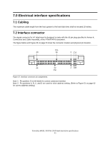
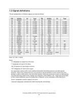
7.4 Signal descriptions DD00-DD15 A 16-bit bi-directional data bus between the host and the HDD. The lower 8 lines, DD00-07, are used for Register and ECC access. All 16 lines, DD00-15, are used for data transfer. These are 3-state lines with 24 mA current sink capability. DA00-DA02 These are addresses used to select the individual register in the HDD. CS0The chip select signal generated from the Host address bus. When active, one of the Command Block Registers [Data, Error (Features when written), Sector Count, Sector Number, Cylinder Low, Cylinder High, Drive/Head and Status (Command when written) register] can be selected. CS1The chip select signal generated from the Host address bus. When active, one of the Control Block Registers [Alternate Status (Device Control when written) and Drive Address register] can be selected. RESETThis line is used to reset the HDD. It shall be kept at a Low logic state during power up and kept High thereafter. DIOWThe rising edge of this signal holds data from the data bus to a register or data register of the HDD. DIORWhen this signal is low, it enables data from a register or data register of the drive onto the data bus. The data on the bus shall be latched on the rising edge of DIOR-. INTRQ The interrupt is enabled only when the drive is selected and the host activates the -IEN bit in the Device Control Register. Otherwise, this signal is in high impedance state regardless of the state of the IRQ bit. The interrupt is set when the IRQ bit is set by the drive CPU. The IRQ is reset to zero by a host read of the status register or a write to the Command Register. This signal is a 3-state line with 24 mA of sink capability. IOCS16A signal indicating to the host that a 16-bit wide data register has been addressed and that the drive is prepared to send or receive a 16-bit wide data word. This signal is an Open-Drain output with 24 mA sink capability and an external resistor is needed to pull this line to 5 volts. DASPThis is a time-multiplexed signal which indicates that a drive is active or that device 1 is present. This signal is driven by an Open-Drain driver and internally pulled up to 5 volts through a 10 kΩ resistor. During a Power-On initialization or after RESET- is negated, DASP- shall be asserted by Device 1 within 400 ms to indicate that device 1 is present. Device 0 shall allow up to 450 ms for device 1 to assert DASP-. If device 1 is not present, device 0 may assert DASP- to drive an LED indicator. The DASP- signal shall be negated following acceptance of the first valid command by device 1. At any moment after negation of DASP-, either drive may assert DASP- to indicate that a drive is active. PDIAG-/CBLIDThis signal shall be asserted by device 1 to indicate to device 0 that it has completed diagnostics. This line is pulled up to 5 volts in the HDD through a 10 kΩ resistor. Travelstar 48GH, 30GN & 15GN hard disk drive specifications 48
-
 1
1 -
2
-
3
-
4
-
5
-
6
-
7
-
8
-
9
-
10
-
11
-
12
-
13
-
14
-
15
-
16
-
17
-
18
-
19
-
20
-
21
-
22
-
23
-
24
-
25
-
26
-
27
-
28
-
29
-
30
-
31
-
32
-
33
-
34
-
35
-
36
-
37
-
38
-
39
-
40
-
41
-
42
-
43
-
44
-
45
-
46
-
47
-
48
-
49
-
50
-
51
-
52
-
53
-
54
-
55
-
56
-
 57
57 -
 58
58 -
 59
59 -
 60
60 -
 61
61 -
 62
62 -
 63
63 -
 64
64 -
 65
65 -
 66
66 -
 67
67 -
68
-
69
-
70
-
71
-
72
-
73
-
74
-
75
-
76
-
77
-
78
-
79
-
80
-
81
-
82
-
83
-
84
-
85
-
86
-
87
-
88
-
89
-
90
-
91
-
92
-
93
-
94
-
95
-
96
-
97
-
98
-
99
-
100
-
101
-
102
-
103
-
104
-
105
-
106
-
107
-
108
-
109
-
110
-
111
-
112
-
113
-
114
-
115
-
116
-
117
-
118
-
119
-
120
-
121
-
122
-
123
-
124
-
125
-
126
-
127
-
128
-
129
-
130
-
131
-
132
-
133
-
134
-
135
-
136
-
137
-
138
-
139
-
140
-
141
-
142
-
143
-
144
-
145
-
146
-
147
-
148
-
149
-
150
-
151
-
152
-
153
-
154
-
155
-
156
-
157
-
158
-
159
-
160
-
161
-
162
-
163
-
164
-
165
-
166
-
167
-
168
-
169
-
170
-
171
-
172
-
173
-
174
-
175
-
176
-
177
-
178
-
179
-
180
-
181
-
182
-
183
-
184
-
185
-
186
-
187
-
188
-
189
-
190
-
191
-
192
-
193
-
194
-
195
-
196
-
197
-
198
-
199
-
200
-
201
-
202
-
203
-
204
-
205
-
206
-
207
-
208
-
209
-
210
-
211
-
212
-
213
-
214
-
215
-
216
-
217
-
218
-
219
-
220
 |
 |
