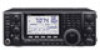
Icom IC-7410 Service Manual - Page 11
Circuit Description, Receiver Circuits, Ctrl Unit, Bpf Unit
 |
View all Icom IC-7410 manuals
Add to My Manuals
Save this manual to your list of manuals |
Page 11 highlights
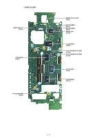
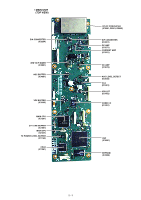
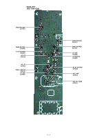
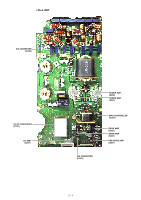
SECTION 3. CIRCUIT DESCRIPTION 3-1 RECEIVER CIRCUITS ANTENNA SWITCHING CIRCUITS (CTRL UNIT) RX signal from the antenna connector [ANT1] (J1) or [ANT2] (J2) is passed through the antenna switch (RL501), current detector (D401), tuner switches (RL351 and RL301), RX line switches (RL601 and RL621) and LPF, and then applied to the BPF UNIT. ATTENUATOR CIRCUITS (BPF UNIT) The RX signal from the CTRL UNIT is passed through or bypassed the attenuator circuit (RL141, R141-R143), depending on the setting. The RX signal, which is passed though or bypassed the attenuator circuit (RL141, R141-R143), is applied to the BPF circuits. PREAMPLIFIER CIRCUITS (BPF UNIT) The RX signal from the BPF circuits is applied to or bypassed the preamplifier. When the Preamplifier function is activated, the RX signal is amplified by one of preamplifiers (Q511, Q512 (for 1.8-2.1 MHz) or Q532 (for 24-50 MHz)). The amplified or bypassed RX signal is applied to the RF-A UNIT. BPF CIRCUITS (BPF UNIT) The RX signal from the attenuator circuits is passed through an LPF or one of BPFs, depending on the operating frequency, to remove unwanted out-of-band signals. The filtered RX signal is applied to or bypassed the preamplifier circuits. • ANTENNA SWITCHING CIRCUITS TO PREAMPLIFIER CIRCUITS To the 1st RX IF circuits Q511/Q512 PRE AMP Q532 PRE AM P 0.03-1.6 MHz LPF 1.6-2.0 MHz BPF 2.0-4.0 MHz BPF 4.0-8.0 MHz BPF 8.0-11.0 MHz BPF 11.0-15.0 MHz BPF 15.0-22.0 MHz BPF 22.0-30.0 MHz BPF 50.0-54.0 MHz BPF 30.0-50.0 MHz 54.0-60.0 MHz BPF ATT RL141 HPF BPF UNIT HF ANT1 HF ANT2 RL501 D401 CURRENT DET RL351 NETWORK UNIT TUNING NETWORK RL621 LPF RL301 RL601 CTRL UNIT 3 - 1
-
 1
1 -
2
-
3
-
4
-
5
-
 6
6 -
 7
7 -
 8
8 -
 9
9 -
 10
10 -
 11
11 -
 12
12 -
 13
13 -
 14
14 -
 15
15 -
 16
16 -
17
-
18
-
19
-
20
-
21
-
22
-
23
-
24
-
25
-
26
-
27
-
28
-
29
-
30
-
31
-
32
-
33
-
34
-
35
-
36
-
37
-
38
-
39
-
40
-
41
-
42
-
43
-
44
-
45
-
46
-
47
-
48
-
49
-
50
-
51
-
52
-
53
-
54
-
55
-
56
-
57
-
58
-
59
-
60
-
61
-
62
-
63
-
64
-
65
-
66
-
67
-
68
-
69
-
70
-
71
-
72
-
73
-
74
-
75
-
76
-
77
-
78
-
79
-
80
-
81
-
82
-
83
-
84
-
85
-
86
-
87
-
88
-
89
-
90
-
91
-
92
-
93
-
94
-
95
-
96
-
97
-
98
-
99
-
100
-
101
-
102
-
103
-
104
-
105
-
106
-
107
-
108
 |
 |
