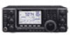
Icom IC-7410 Service Manual - Page 14
Rf-a Unit, Bpf Unit, 3rd Tx If And 2nd Tx If Circuits, 1st Tx If Circuits
 |
View all Icom IC-7410 manuals
Add to My Manuals
Save this manual to your list of manuals |
Page 14 highlights
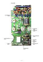
3RD TX IF AND 2ND TX IF CIRCUITS (MAIN UNIT) The 3rd TX IF signal from the modulation circuits is amplified by two AMPs (IC4661 and IC3601), and then applied to the 3rd TX mixer (IC3621) to be mixed with the 3rd TX LO signal from the PLL UNIT, resulting in the 455 kHz 2nd TX IF signal. The converted 2nd TX IF signal is amplified by the IF AMP (Q3631), and then passed though the 2nd TX filter (FI3641). The filtered 2nd TX IF signal is amplified by the 2nd TX IF AMP (Q3651), and then applied to the 2nd TX mixer (D3671). The 2nd TX IF signal is mixed with the 64 MHz 2nd TX LO signal from the PLL UNIT, resulting in the 64.455 MHz 1st TX IF signal. The 1st TX IF signal is applied to the 1st TX IF circuits on the RF-A UNIT. • 3RD TX IF AND 2ND TX IF CIRCUITS From the modulation circuits IC4661 AMP IC3601 AMP IC3621 Q3631 IF AMP FI3641 CERAMIC BPF Q3651 IF AMP D3671 64.455 MHz BPF To the 1st TX IF circuits 491 kHz T3LO From the PLL UNIT 455kHz(BW=20k) IC3675 T2LO 64 MHz ATT From the PLL UNIT LO ATT AMP 1ST TX IF CIRCUITS (RF-A UNIT) The 1st TX IF signal from the 2nd TX IF circuits is passed through the 1st TX IF filter (FI911) to remove unwanted signals. The filtered signal is amplified by the IF AMP (Q611), and then applied to the 1st TX mixer (D651), through the LPF. The 1st TX IF signal is mixed with the 1st TX LO signal from the PLL UNIT, resulting in the TX signal (TX frequency itself). The converted TX signal is passed through the LPF, and amplified by the AMP (IC601), and then applied to the BPF circuits. BPF CIRCUITS The TX signal from the 1st TX IF circuits is passed through an LPF or one of BPFs, depending on the transmitting frequency, to remove unwanted signals contained in the TX signal. The filtered TX signal is amplified by the YGR AMP (IC201), and then applied to the PA-A UNIT, through the BPF. • BPF CIRCUITS From the 1st TX IF circuits 0.03-1.6 MHz LPF 1.6-2.0 MHz BPF HPF IC201 YGR AMP To the TX amplifier circuits BPF 2.0-4.0 MHz BPF 4.0-8.0 MHz BPF 8.0-11.0 MHz BPF BPF UNIT 11.0-15.0 MHz BPF 15.0-22.0 MHz BPF 22.0-30.0 MHz BPF 50.0-54.0 MHz BPF 30.0-50.0 MHz 54.0-60.0 MHz BPF • 1ST TX IF CIRCUITS From the 2nd TX IF circuits FI911 64.455 MHz(BW=15 kHz) XTAL BPF Q611 IF AMP LPF D651 LPF IC601 IF AMP 64.485~ 124.455 MHz Q811 LO LPF AMP To the BPF circuits 1st TX LO LPF LPF RF-A UNIT 3 - 4
-
 1
1 -
2
-
3
-
4
-
5
-
6
-
7
-
8
-
 9
9 -
 10
10 -
 11
11 -
 12
12 -
 13
13 -
 14
14 -
 15
15 -
 16
16 -
 17
17 -
 18
18 -
 19
19 -
20
-
21
-
22
-
23
-
24
-
25
-
26
-
27
-
28
-
29
-
30
-
31
-
32
-
33
-
34
-
35
-
36
-
37
-
38
-
39
-
40
-
41
-
42
-
43
-
44
-
45
-
46
-
47
-
48
-
49
-
50
-
51
-
52
-
53
-
54
-
55
-
56
-
57
-
58
-
59
-
60
-
61
-
62
-
63
-
64
-
65
-
66
-
67
-
68
-
69
-
70
-
71
-
72
-
73
-
74
-
75
-
76
-
77
-
78
-
79
-
80
-
81
-
82
-
83
-
84
-
85
-
86
-
87
-
88
-
89
-
90
-
91
-
92
-
93
-
94
-
95
-
96
-
97
-
98
-
99
-
100
-
101
-
102
-
103
-
104
-
105
-
106
-
107
-
108
 |
 |
