Icom IC-7410 Service Manual - Page 4
SPECIFICATIONS, General, Transmitter, Receiver, Antenna tuner - weight
 |
View all Icom IC-7410 manuals
Add to My Manuals
Save this manual to your list of manuals |
Page 4 highlights
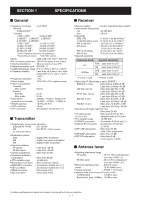
SECTION 1. SPECIFICATIONS ■ General • Frequency coverage : (unit: MHz) Receive 0.030-60.000*1*2 Transmit 1.800-1.999*2, 3.500-3.999*2, 5.330500*3, 5.346500*3, 5.366500*3, 5.371500*3, 5.403500*3, 7.000-7.300*2, 10.100-10.150*2, 14.000-14.350*2, 18.068-18.168*2, 21.000-21.450*2, 24.890-24.990*2, 28.000-29.700*2, 50.000-54.000*2 *1Some frequency bands are not guaranteed. *2Depending on version. *3Only USA version. • Mode : USB, LSB, CW, RTTY, AM, FM • No. of memory channels : 101CH (99 regular, 2 scan edges) • Antenna impedance : 50 Ω (at Antenna Tuner OFF) • Antenna connector type : SO-239 × 2 • Usable temperature range : 0˚C to +50˚C (+32˚F to +122˚F) • Frequency stability : Less than ±0.5 ppm 5 min. after power ON. (0˚C to +50˚C; +32˚F to • Frequency resolution • Power supply • Power consumption Transmit Max. power Receive Standby Max. audio • Dimensions (projections not included) • Weight (approx.) • ACC connector • CI-V connector +122˚F) : 1 Hz : 13.8 V DC ±15% (negative ground) : 23.0 A : 2.2 A : 3.0 A : 315(W) × 116(H) × 343(D) mm 12.4(W) × 4.57(H) × 13.5(D) in : 10.2 kg; 22.4 lb : 13-pin : 2-conductor 3.5 (d) mm (1⁄8″) ■ Transmitter • Output power (continuously adjustable) SSB/CW/RTTY/FM : 2 to 100 W AM : 2 to 27 W* (*Carrier power) (at 13.8 V DC/+25˚C) • Modulation system SSB AM FM • Spurious emission HF bands 50 MHz band • Carrier suppression • Unwanted sideband suppression • TX variable range • Microphone connector • ELEC-KEY connector • KEY connector • SEND connector • ALC connector : Digital PSN modulation : Digital Low power modulation : Digital Phase modulation : Less than -50 dB : Less than -63 dB : More than 40 dB : More than 55 dB : ±9.999 kHz : 8-pin connector (600 Ω) : 3-conductor 6.35(d) mm (1⁄4″) : 3-conductor 6.35(d) mm (1⁄4″) : Phono jack (RCA) : Phono jack (RCA) ■ Receiver • Receive system : Double superheterodyne system • Intermediate frequencies 1st : 64.455 MHz 2nd : 36 kHz • Sensitivity SSB, CW : 0.16 µV (1.80-29.99 MHz)*4 (10 dB S/N) BW=2.4 kHz 0.13 µV (50.0-54.0 MHz)*5 AM (10 dB S/N) : 12.6 µV (0.5-1.799 MHz)*4 BW=6 kHz 2.0 µV (1.80-29.99 MHz)*4 1.6 µV (50.0-54.0 MHz)*5 FM (12 dB SINAD) : 0.5 µV (28.0-29.7 MHz)*4 BW=15 kHz 0.32 µV (50.0-54.0 MHz)*5 • Squelch sensitivity Frequency band Squelch sensitivity SSB : Less than 5.6 µV*4 HF FM : Less than 0.32 µV*4 50 MHz SSB : Less than 5.6 µV*5 FM : Less than 0.32 µV*5 *4 Preamp 1 is ON. *5 Preamp 2 is ON. • Selectivity (IF filter shape is set to SHARP.) SSB (BW: 2.4 kHz) : More than 2.4 kHz/-6 dB Less than 3.4 kHz/-40 dB CW (BW: 500 Hz) : More than 500 Hz/-6 dB Less than 700 Hz/-40 dB RTTY (BW: 350 Hz) : More than 500 Hz/-6 dB Less than 800 Hz/-40 dB AM (BW: 6 kHz) : More than 6.0 kHz/-6 dB Less than 10.0 kHz/-40 dB FM (BW: 15 kHz) : More than 12.0 kHz/-6 dB Less than 22.0 kHz/-40 dB • Spurious and image rejection ratio : More than 70 dB • AF output power : More than 2.0 W at 10% (at 13.8 V DC) distortion with an 8 Ω load • RIT variable range : ±9.999 kHz • PHONES connector : 3-conductor 6.35 (d) mm (1⁄4″) • External SP connector : 2-conductor 3.5 (d) mm (1⁄8″)/8 Ω • DSP ANF attenuation : More than 30 dB (with 1 kHz single tone) • DSP MNF attenuation : More than 70 dB • DSP NR attenuation : More than 6 dB (noise rejection in SSB) ■ Antenna tuner • Matching impedance range HF bands : 16.7 to 150 Ω unbalanced (Less than VSWR 1:3) 50 MHz band : 20 to 125 Ω unbalanced (Less than VSWR 1:2.5) • Minimum operating input : 8 W (HF bands) power 15 W (50MHz band ) • Tuning accuracy : VSWR 1:1.5 or less • Insertion loss (after tuning at RF power 100W) 1.8 MHz band : 1.2 dB or less Bands other than 1.8 MHz : 1.0 dB or less All stated specifications are typical and subject to change without notice or obligation. 1 - 1
-
 1
1 -
 2
2 -
 3
3 -
 4
4 -
 5
5 -
 6
6 -
 7
7 -
 8
8 -
 9
9 -
 10
10 -
11
-
12
-
13
-
14
-
15
-
16
-
17
-
18
-
19
-
20
-
21
-
22
-
23
-
24
-
25
-
26
-
27
-
28
-
29
-
30
-
31
-
32
-
33
-
34
-
35
-
36
-
37
-
38
-
39
-
40
-
41
-
42
-
43
-
44
-
45
-
46
-
47
-
48
-
49
-
50
-
51
-
52
-
53
-
54
-
55
-
56
-
57
-
58
-
59
-
60
-
61
-
62
-
63
-
64
-
65
-
66
-
67
-
68
-
69
-
70
-
71
-
72
-
73
-
74
-
75
-
76
-
77
-
78
-
79
-
80
-
81
-
82
-
83
-
84
-
85
-
86
-
87
-
88
-
89
-
90
-
91
-
92
-
93
-
94
-
95
-
96
-
97
-
98
-
99
-
100
-
101
-
102
-
103
-
104
-
105
-
106
-
107
-
108
 |
 |