Icom IC-7410 Service Manual - Page 12
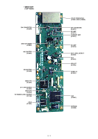
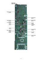
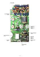
Rf-a Unit, 1st Rx If And 2nd Rx If Circuits, Demodulator Circuits, 1st Rx If Circuits Rf-a Unit
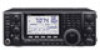 |
View all Icom IC-7410 manuals
Add to My Manuals
Save this manual to your list of manuals |
Page 12 highlights
1ST RX IF CIRCUITS (RF-A UNIT) The RX signal from the BPF UNIT is passed through the LPF, which removes unwanted signals (60 MHz and higher), and then applied to the 1st RX IF mixer (Q721-Q724) to be mixed with the 1st RX LO signal (64.485-124.455 MHz) from the PLL UNIT, resulting in the 64.455 MHz 1st RX IF signal. The 1st RX IF signal is amplified by the 1st RX IF AMP (Q741) and passed through one of the 1st IF filters (FI911; FL-434, or optional FL-430 or FL-431), which has different passband widths, according to the IF filter setting. The filtered 1st RX IF signal is amplified by the RX IF AMPs (Q1051 and Q1071, Q1072), and then applied to the 2nd RX IF circuits. 2ND RX IF CIRCUITS (RF-A UNIT) The 1st RX IF signal from the 1st RX IF circuits is divided into two paths, and then each signal is applied to the 2nd RX IF mixers (the image reduction mixers; D1102/D1101) to be mixed with the 2nd RX LO signal (64.491 MHz) from the PLL UNIT, resulting in the 36 kHz 2nd RX IF signal. The image reduction mixer removes image frequency components by using two LO signals which are 90 degrees phase-shifted from each other. The 2nd RX IF signals are independently amplified by the buffers (Q1201/Q1251) and IF AMPs (IC1221). These amplified 2nd RX IF signals are 90 degrees phaseshifted and combined by the combiner (IC1222), and then applied to the MAIN UNIT. • 1ST RX IF AND 2ND RX IF CIRCUITS IC1222 IC1222 To the demodulator circuits Σ 90deg IC1221 IF AMP Q1201 BUFF IC1221 IF AMP Q1251 BUFF D1102 Q1071/Q1072 IF AMP Q1051 IF AMP D1101 FI911 64.455MHz(BW=15kHz) XTAL BPF FL-430(Optional) 64.455MHz(BW=6kHz) XTAL BPF IC1121 BUFF FL-431(Optional) 64.455MHz(BW=3kHz) XTAL BPF IC1121 BUFF 90deg IC1121 BUFF Q1141 LO AMP ATT 2nd RX LO Q721/Q722/ fc=60MHz Q741 Q723/Q724 ATT IF AMP LPF From the preamplifier circuits Q811 64.485~ 124.455 MHz LPF LO AMP 1st RX/TX LO LPF LPF RF-A UNIT DEMODULATOR CIRCUITS (MAIN UNIT) The 2nd RX IF signal from the 2nd RX IF circuits is passed through the RX mute SW (IC4604) and the balanceunbalance converter (Balun; IC4602/IC4603), and then applied to the CODEC (IC4651) to be converted into digital audio signal. The converted digital audio signal is applied to the DSP (IC4001), and demodulated and processed. The demodulated signal is applied to another CODEC (IC4461) to be converted into analog AF signal, and then applied to the buffer amplifier (IC4483). The buffer amplified AF signal is applied to the CONNECT UNIT. • DEMODULATOR CIRCUITS IC4461 IC4483 To the RX AF circuits AMP IC4001 DSP IC4651 IC4603 LPF IC4603 LPF IC4602 BUFF IC4604 MUTE From the 2nd RX circuits CODEC CODEC IC1201 MAIN CPU IC1261 CPLD MAIN UNIT 3 - 2
-
 1
1 -
2
-
3
-
4
-
5
-
6
-
 7
7 -
 8
8 -
 9
9 -
 10
10 -
 11
11 -
 12
12 -
 13
13 -
 14
14 -
 15
15 -
 16
16 -
 17
17 -
18
-
19
-
20
-
21
-
22
-
23
-
24
-
25
-
26
-
27
-
28
-
29
-
30
-
31
-
32
-
33
-
34
-
35
-
36
-
37
-
38
-
39
-
40
-
41
-
42
-
43
-
44
-
45
-
46
-
47
-
48
-
49
-
50
-
51
-
52
-
53
-
54
-
55
-
56
-
57
-
58
-
59
-
60
-
61
-
62
-
63
-
64
-
65
-
66
-
67
-
68
-
69
-
70
-
71
-
72
-
73
-
74
-
75
-
76
-
77
-
78
-
79
-
80
-
81
-
82
-
83
-
84
-
85
-
86
-
87
-
88
-
89
-
90
-
91
-
92
-
93
-
94
-
95
-
96
-
97
-
98
-
99
-
100
-
101
-
102
-
103
-
104
-
105
-
106
-
107
-
108
 |
 |
