Insignia NS-P501Q-10A User Manual (English) - Page 9
TV components - remote
 |
UPC - 600603123757
View all Insignia NS-P501Q-10A manuals
Add to My Manuals
Save this manual to your list of manuals |
Page 9 highlights
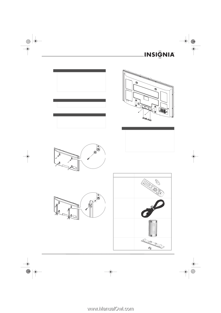
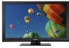
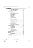
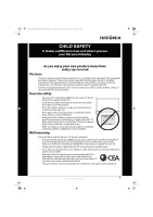
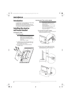
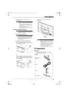
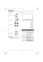
NS-P42Q-P501Q-P502Q-10A_09-0100_MAN_V1_English.book Page 5 Friday, March 20, 2009 3:11 PM 3 Tie the anti-fall device cord to the wall or cabinet screw. Warning • Install the TV close to the wall so that it does not fall. • When attaching the TV to the wall, tie the cord level with the ground or slanted downwards for safety purposes. • Check the anti-fall cord frequently to make sure that it does not come loose. • Before moving your TV, untie the anti-fall cord. Installing a wall-mount bracket Warning This apparatus is intended to be supported by a UL Listed wall-mount bracket. To install a wall-mount bracket: Warning These servicing instructions are for use by qualified service personnel only. To reduce the risk of hazards, do not perform any servicing other than that contained in the operating instructions unless you are qualified to do so. 1 If the stand is installed, remove the stand. 2 For an Insignia wall-mount kit, attach the wall-mount bracket to the back of your TV using four M8 screws (included). Insignia wall mount Screw Or, For a non-Insignia wall-mount kit, attach the wall-mount bracket to the back of your TV using four screw-holder rings (included) and four M8 screws (included). Non-Insignia wall mount 3 Install the base cover using two screws (included). Warning • Do not use screws longer than the standard dimension, because they may cause damage to the inside of your TV. • For wall mounts that do not comply with the VESA standard screw specifications, the length of the required screws may differ. Do not use screws that do not comply with the VESA standard screw specifications. • Do not exceed a 15° tilt when mounting your TV. TV components Accessories Make sure that the following accessories are provided in the packaging: Accessories Remote control with two AAA batteries Screw-holder ring Power cord Ferrite core Base cover with screws www.insigniaproducts.com 5
-
 1
1 -
2
-
3
-
 4
4 -
 5
5 -
 6
6 -
 7
7 -
 8
8 -
 9
9 -
 10
10 -
 11
11 -
 12
12 -
 13
13 -
 14
14 -
15
-
16
-
17
-
18
-
19
-
20
-
21
-
22
-
23
-
24
-
25
-
26
-
27
-
28
-
29
-
30
-
31
-
32
-
33
-
34
-
35
-
36
-
37
-
38
-
39
-
40
-
41
-
42
-
43
-
44
-
45
-
46
-
47
-
48
-
49
-
50
-
51
-
52
 |
 |