Intel A2400SATAKIT Installation Guide - Page 10
Document Scope and Assumptions, Tools and Supplies Needed
 |
View all Intel A2400SATAKIT manuals
Add to My Manuals
Save this manual to your list of manuals |
Page 10 highlights
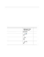
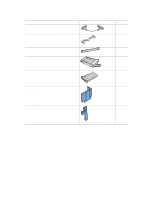
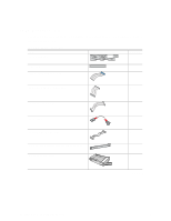
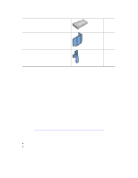
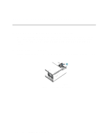
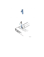
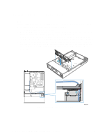
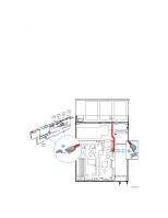
SATA Backplane Parts List (continued) Drive bay blank 1 Large air baffle 1 Small air baffle 1 Document Scope and Assumptions This document provides instructions to guide you through installing the hot-swap SCSI or hot-swap SATA backplane into the Intel® Server Chassis SR2400. The server board diagrams in this document are specific to the Intel® Server Board SE7520JR2 and Intel® Server Board SE7320VP2, although this kit may work with other Intel® Server Boards as well. For boards other than the Server Board SE7520JR2 or Server Board SE7320VP2, refer to the documentation that came with your server board to determine compatibility and cable routing. This document assumes you are installing the backplane kit during an initial integration process, before your server system is up and running. Because the Quick Start User's Guide used for the initial integration is used for several implementations, this instruction guide will ask you to uninstall selected components that you may have just installed. For the best results, read through both the Quick Start User's Guide and this installation guide before beginning your installation. If you are installing the backplane board into a fully integrated server system that is currently operational, you will need to uninstall several components. Refer to the Intel® Server Chassis SR2400 User Guide for instructions on removing and reinstalling components. The User's Guide is available at http://support.intel.com/support/motherboards/server/chassis/SR2400/ Tools and Supplies Needed • Phillips* (cross head) screwdriver (#2 bit) • Anti-static wrist strap (recommended) 4 Intel® Server Chassis SR2400 SCSI and SATA Backplane Installation Instructions
-
 1
1 -
2
-
3
-
4
-
 5
5 -
 6
6 -
 7
7 -
 8
8 -
 9
9 -
 10
10 -
 11
11 -
 12
12 -
 13
13 -
 14
14 -
 15
15 -
16
-
17
-
18
-
19
-
20
-
21
-
22
-
23
-
24
-
25
 |
 |
