Intel BLKD945GCLF2D Product Specification - Page 45
Add-in Card Connectors, 2.2.3, Power Supply Connectors
 |
View all Intel BLKD945GCLF2D manuals
Add to My Manuals
Save this manual to your list of manuals |
Page 45 highlights
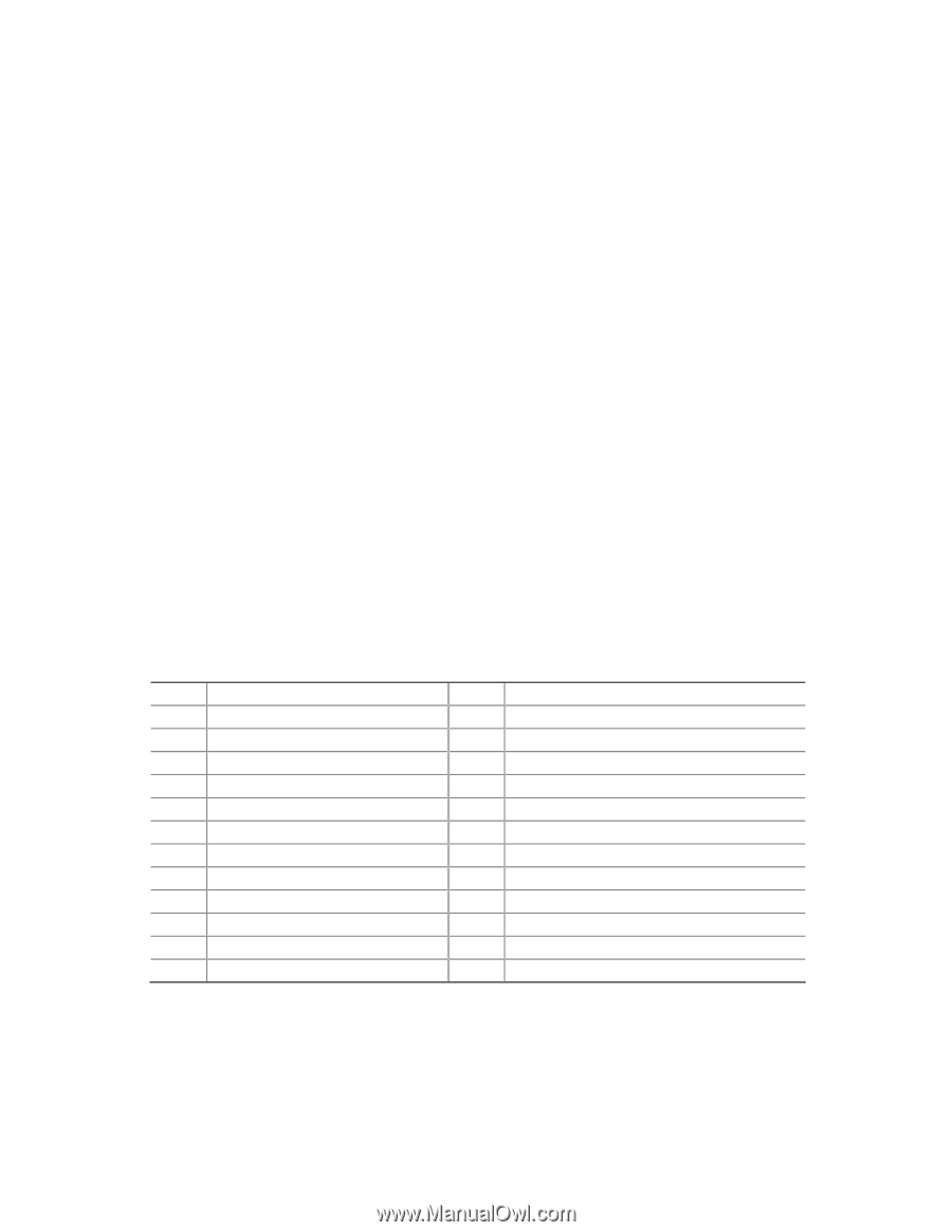
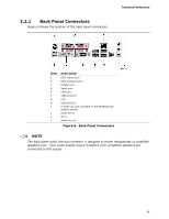
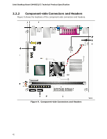
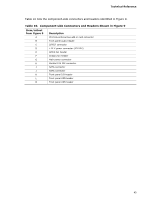
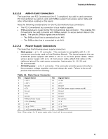
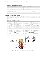
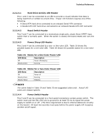
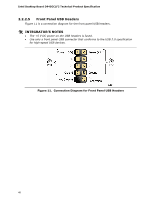
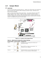
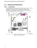
Technical Reference 2.2.2.2 Add-in Card Connectors The board has one PCI Conventional (rev 2.3 compliant) bus add-in card connector. PCI Conventional bus add-in cards with SMBus support can access sensor data and other information residing on the board. Note the following considerations for the PCI Conventional bus connectors: • The PCI Conventional bus connector is bus master capable. • SMBus signals are routed to the PCI Conventional bus connector. This enables PCI Conventional bus add-in boards with SMBus support to access sensor data on the board. The specific SMBus signals are as follows: ⎯ The SMBus clock line is connected to pin A40. ⎯ The SMBus data line is connected to pin A41. 2.2.2.3 Power Supply Connectors The board has the following power supply connectors: • Main power - a 2 x 12 connector. This connector is compatible with 2 x 10 connectors previously used on Intel Desktop Boards. The board supports the use of ATX12V power supplies with either 2 x 10 or 2 x 12 main power cables. When using a power supply with a 2 x 10 main power cable, attach that cable on the rightmost pins of the main power connector, leaving pins 11, 12, 23, and 24 unconnected. • ATX12V power - a 2 x 2 connector. This connector provides power directly to the processor voltage regulator and must always be used. Failure to do so will prevent the board from booting. Table 16. Main Power Connector Pin Signal Name 1 +3.3 V Pin Signal Name 13 +3.3 V 2 +3.3 V 14 -12 V 3 Ground 4 +5 V 5 Ground 6 +5 V 15 Ground 16 PS-ON# (power supply remote on/off) 17 Ground 18 Ground 7 Ground 8 PWRGD (Power Good) 9 +5 V (Standby) 10 +12 V 11 +12 V (Note) 12 2 x 12 connector detect (Note) 19 Ground 20 No connect 21 +5 V 22 +5 V 23 +5 V (Note) 24 Ground (Note) Note: When using a 2 x 10 power supply cable, this pin will be unconnected. 45
-
 1
1 -
2
-
3
-
4
-
5
-
6
-
7
-
8
-
9
-
10
-
11
-
12
-
13
-
14
-
15
-
16
-
17
-
18
-
19
-
20
-
21
-
22
-
23
-
24
-
25
-
26
-
27
-
28
-
29
-
30
-
31
-
32
-
33
-
34
-
35
-
36
-
37
-
38
-
39
-
 40
40 -
 41
41 -
 42
42 -
 43
43 -
 44
44 -
 45
45 -
 46
46 -
 47
47 -
 48
48 -
 49
49 -
 50
50 -
51
-
52
-
53
-
54
-
55
-
56
-
57
-
58
-
59
-
60
-
61
-
62
-
63
-
64
-
65
-
66
-
67
-
68
-
69
-
70
-
71
-
72
-
73
-
74
-
75
-
76
-
77
-
78
-
79
-
80
-
81
-
82
-
83
-
84
 |
 |