Intel BLKD945GSEJT Product Guide - Page 32
Connecting SATA Drives, Removing System Memory
 |
View all Intel BLKD945GSEJT manuals
Add to My Manuals
Save this manual to your list of manuals |
Page 32 highlights
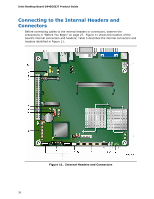
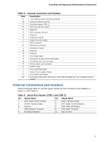
Intel Desktop Board D945GSEJT Product Guide To remove an SO-DIMM from the socket, gently spread the socket's retention arms as shown in Figure 7 to disengage them from the SO-DIMM. Figure 7. Removing System Memory Connecting SATA Drives Intel Desktop Board D945GSEJT supports two SATA drives with two data connectors. The board ships with an in-line power cable that provides: • a right-angled female-gender 1 x 4 connector for low-profile board connectivity • a 15-pin SATA power connector for SATA drive power • a female-gender 1 x 4 connector for system component power flexibility To connect a SATA drive to the Desktop Board: 1. Observe the precautions in "Before You Begin" on page 27. 2. Attach one end of the SATA data cable to a SATA connector on the board (Figure 8, A). 3. Attach the other end of the SATA data cable to the SATA drive (Figure 8, B). 4. Attach the right-angled 4-pin power connector on the power cable to the 4-pin connector on the Desktop Board (Figure 8, C). 5. Attach the SATA power connector (Figure 8, D) on the power cable to the mating connector on a SATA drive. 32
-
 1
1 -
2
-
3
-
4
-
5
-
6
-
7
-
8
-
9
-
10
-
11
-
12
-
13
-
14
-
15
-
16
-
17
-
18
-
19
-
20
-
21
-
22
-
23
-
24
-
25
-
26
-
 27
27 -
 28
28 -
 29
29 -
 30
30 -
 31
31 -
 32
32 -
 33
33 -
 34
34 -
 35
35 -
 36
36 -
 37
37 -
38
-
39
-
40
-
41
-
42
-
43
-
44
-
45
-
46
-
47
-
48
-
49
-
50
-
51
-
52
-
53
-
54
-
55
-
56
-
57
-
58
-
59
-
60
-
61
-
62
-
63
-
64
-
65
-
66
-
67
-
68
-
69
-
70
-
71
-
72
 |
 |
