Intel BLKD945GSEJT Product Guide - Page 43
Table 21. Front Panel Header, Connection Diagram for Front Panel Header
 |
View all Intel BLKD945GSEJT manuals
Add to My Manuals
Save this manual to your list of manuals |
Page 43 highlights
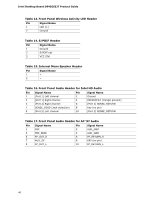
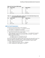
Installing and Replacing Desktop Board Components Table 21. Front Panel Header Pin Signal In/ Out Description Pin Hard Drive Activity LED 1 HD_PWR Out Hard disk LED 2 pull-up to +5 V 3 HDA# Out Hard disk active 4 LED Reset Switch 5 Ground Ground 6 7 FP_RESET# In Reset switch 8 Power 9 +5 V Power 10 Signal In/ Out Description Power LED HDR_BLNK_GR Out N Front panel green LED HDR_BLNK_YE Out L Front panel yellow LED On/Off Switch FPBUT_IN Ground In Power switch Ground Not Connected N/C Not connected Figure 12. Connection Diagram for Front Panel Header Hard Drive Activity LED Pins Pins 1 and 3 can be connected to an LED to provide a visual indicator that data is being read from or written to a hard drive. Proper LED function requires one of the following: • A SATA hard drive connected to an onboard SATA connector • A PATA hard drive connected to an onboard PATA connector • Intel Z-U130 USB Solid State Drive (or compatible device) connected to one of the front panel USB headers Reset Switch Pins Pins 5 and 7 can be connected to a momentary single pole, single throw (SPST) type switch that is normally open. When the switch is closed, the board resets and runs the POST. 43
-
 1
1 -
2
-
3
-
4
-
5
-
6
-
7
-
8
-
9
-
10
-
11
-
12
-
13
-
14
-
15
-
16
-
17
-
18
-
19
-
20
-
21
-
22
-
23
-
24
-
25
-
26
-
27
-
28
-
29
-
30
-
31
-
32
-
33
-
34
-
35
-
36
-
37
-
 38
38 -
 39
39 -
 40
40 -
 41
41 -
 42
42 -
 43
43 -
 44
44 -
 45
45 -
 46
46 -
 47
47 -
 48
48 -
49
-
50
-
51
-
52
-
53
-
54
-
55
-
56
-
57
-
58
-
59
-
60
-
61
-
62
-
63
-
64
-
65
-
66
-
67
-
68
-
69
-
70
-
71
-
72
 |
 |
