Intel BLKD946GZABL Product Specification - Page 31
Thermal Monitoring
 |
View all Intel BLKD946GZABL manuals
Add to My Manuals
Save this manual to your list of manuals |
Page 31 highlights
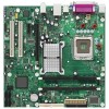
Product Description 1.9.4 Thermal Monitoring Figure 10 shows the locations of the thermal sensors and fan headers. E B D A C F Item A B C D E F Description Remote thermal sensor Thermal diode, located on processor die Hardware monitoring and fan control ASIC Processor fan Rear chassis fan Front chassis fan Figure 10. Thermal Sensors and Fan Headers OM18382 31
-
 1
1 -
2
-
3
-
4
-
5
-
6
-
7
-
8
-
9
-
10
-
11
-
12
-
13
-
14
-
15
-
16
-
17
-
18
-
19
-
20
-
21
-
22
-
23
-
24
-
25
-
 26
26 -
 27
27 -
 28
28 -
 29
29 -
 30
30 -
 31
31 -
 32
32 -
 33
33 -
 34
34 -
 35
35 -
 36
36 -
37
-
38
-
39
-
40
-
41
-
42
-
43
-
44
-
45
-
46
-
47
-
48
-
49
-
50
-
51
-
52
-
53
-
54
-
55
-
56
-
57
-
58
-
59
-
60
-
61
-
62
-
63
-
64
-
65
-
66
-
67
-
68
-
69
-
70
-
71
-
72
-
73
-
74
-
75
-
76
-
77
-
78
-
79
-
80
-
81
-
82
-
83
-
84
-
85
-
86
-
87
-
88
-
89
-
90
 |
 |

Product Description
31
1.9.4
Thermal Monitoring
Figure 10 shows the locations of the thermal sensors and fan headers.
OM18382
F
E
B
D
A
C
Item
Description
A
Remote thermal sensor
B
Thermal diode, located on processor die
C
Hardware monitoring and fan control ASIC
D
Processor fan
E
Rear chassis fan
F
Front chassis fan
Figure 10.
Thermal Sensors and Fan Headers