Intel BOXD865GLCL Product Specification - Page 14
Board Layouts
 |
UPC - 735858159869
View all Intel BOXD865GLCL manuals
Add to My Manuals
Save this manual to your list of manuals |
Page 14 highlights
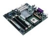
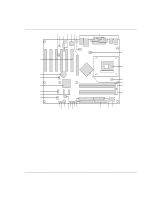
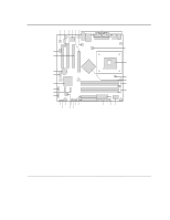
Intel Desktop Board D865GBF/D865GLC Technical Product Specification 1.2.3 Board Layouts Figure 1 shows the location of the major components on the Desktop Board D865GBF. A D EF H BC G I FF J EE DD K L CC M BB N AA Z Y W U SR X VT Q PO OM15914 A Auxiliary line-in connector B Audio codec C Front panel audio connector D ATAPI CD-ROM connector E Ethernet PLC device (Optional) F AGP connector G Rear chassis fan connector H Back panel connectors I +12V power connector (ATX12V) J mPGA478 processor socket K Processor fan connector L Intel 82865G GMCH M DIMM Channel A sockets N DIMM Channel B sockets O I/O controller P Power connector Q Diskette drive connector R Parallel ATA IDE connectors S SCSI hard drive activity LED connector (optional) T Front chassis fan connector U Chassis intrusion connector V 4 Mbit Firmware Hub (FWH) W Speaker X BIOS Setup configuration jumper block Y Auxiliary front panel power LED connector Z Front panel connector AA Serial ATA connectors BB Front panel USB connector CC Intel 82801EB I/O Controller Hub (ICH5) DD Front panel USB connector EE Battery FF PCI bus add-in card connectors Figure 1. Desktop Board D865GBF Components 14
-
 1
1 -
2
-
3
-
4
-
5
-
6
-
7
-
8
-
 9
9 -
 10
10 -
 11
11 -
 12
12 -
 13
13 -
 14
14 -
 15
15 -
 16
16 -
 17
17 -
 18
18 -
 19
19 -
20
-
21
-
22
-
23
-
24
-
25
-
26
-
27
-
28
-
29
-
30
-
31
-
32
-
33
-
34
-
35
-
36
-
37
-
38
-
39
-
40
-
41
-
42
-
43
-
44
-
45
-
46
-
47
-
48
-
49
-
50
-
51
-
52
-
53
-
54
-
55
-
56
-
57
-
58
-
59
-
60
-
61
-
62
-
63
-
64
-
65
-
66
-
67
-
68
-
69
-
70
-
71
-
72
-
73
-
74
-
75
-
76
-
77
-
78
-
79
-
80
-
81
-
82
-
83
-
84
-
85
-
86
-
87
-
88
-
89
-
90
-
91
-
92
-
93
-
94
-
95
-
96
-
97
-
98
-
99
-
100
-
101
-
102
-
103
-
104
-
105
-
106
-
107
-
108
-
109
-
110
-
111
-
112
-
113
-
114
-
115
-
116
-
117
-
118
-
119
-
120
-
121
-
122
-
123
-
124
-
125
-
126
-
127
-
128
-
129
-
130
-
131
-
132
-
133
-
134
-
135
-
136
-
137
-
138
-
139
-
140
-
141
-
142
 |
 |
