Intel D34010WYK Technical Product Specification - Page 41
Table 13., Connectors and Headers Shown
 |
View all Intel D34010WYK manuals
Add to My Manuals
Save this manual to your list of manuals |
Page 41 highlights
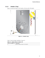
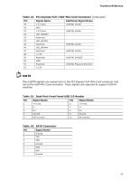
Technical Reference Table 13 lists the connectors and headers identified in Figure 10. Table 13. Connectors and Headers Shown in Figure 10 Item from Figure 10 Description A PCI Express Full-Mini Card connector B PCI Express Half-Mini Card connector C SATA 6.0 Gb/s connector through the PCH D Front panel dual-port USB 2.0 header (2.0 mm pitch) E Front panel header (2.0 mm pitch) F SATA power connector G BIOS setup configuration jumper H Internal DC power connector 41
-
 1
1 -
2
-
3
-
4
-
5
-
6
-
7
-
8
-
9
-
10
-
11
-
12
-
13
-
14
-
15
-
16
-
17
-
18
-
19
-
20
-
21
-
22
-
23
-
24
-
25
-
26
-
27
-
28
-
29
-
30
-
31
-
32
-
33
-
34
-
35
-
 36
36 -
 37
37 -
 38
38 -
 39
39 -
 40
40 -
 41
41 -
 42
42 -
 43
43 -
 44
44 -
 45
45 -
 46
46 -
47
-
48
-
49
-
50
-
51
-
52
-
53
-
54
-
55
-
56
-
57
-
58
-
59
-
60
-
61
-
62
-
63
-
64
-
65
-
66
-
67
-
68
-
69
-
70
-
71
-
72
-
73
-
74
-
75
-
76
-
77
-
78
 |
 |

Technical Reference
41
Table 13 lists the connectors and headers identified in Figure 10.
Table 13.
Connectors and Headers Shown in Figure 10
Item from
Figure 10
Description
A
PCI Express Full-Mini Card connector
B
PCI Express Half-Mini Card connector
C
SATA 6.0 Gb/s connector through the PCH
D
Front panel dual-port USB 2.0 header (2.0 mm pitch)
E
Front panel header (2.0 mm pitch)
F
SATA power connector
G
BIOS setup configuration jumper
H
Internal DC power connector