Intel D34010WYK Technical Product Specification - Page 47
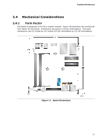
System ID / Custom Solutions Header 2.0 mm Pitch
 |
View all Intel D34010WYK manuals
Add to My Manuals
Save this manual to your list of manuals |
Page 47 highlights
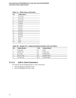
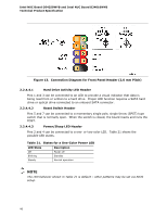
Technical Reference 2.2.4.4.4 Power Switch Header Pins 6 and 8 can be connected to a front panel momentary-contact power switch. The switch must pull the SW_ON# pin to ground for at least 50 ms to signal the power supply to switch on or off. (The time requirement is due to internal debounce circuitry on the board.) At least two seconds must pass before the power supply will recognize another on/off signal. 2.2.4.5 System ID / Custom Solutions Header (2.0 mm Pitch) The System ID / Customs Solution header is provided to aid customers in developing custom applications. • Prog_LED#: general purpose signal output that indicates when an event was triggered by the operating system. Signal is amplified by a transistor. Intel can provide sample code for customers who may want to write their own applications leveraging this signal. • SMB_CLK and SMB_DATA: SMBus interface, reserved for future support of All-InOne chassis detection. General SMBus information can be found on the platform EDS and at http://smbus.org/specs/. • 3.3 V Standby: can be used to monitor the presence of 3.3 V standby power. • PWRBT#: power button signal (functions in the same manner as the power button pin on the front panel header). • HDMI Consumer Electronics Control (CEC): standard communication signal from the Mini HDMI connector (http://www.hdmi.org/) - the signal is exposed through this header for third party solutions to monitor/control CEC activity between multiple HDMI devices. • 5 V Standby: can be used to monitor the presence of 5 V Standby power or provide power from the 5 V Standby rail (up to 2A current rating). • SCI/SMI GPI: input signal for direct connection to a front panel push-button to trigger a Windows command. Intel will be adding BIOS support and accompanying Windows utility to enable Direct Application Launch* feature. General information about Direct Application Launch can be found at: http://msdn.microsoft.com/en-us/windows/hardware/gg463078.aspx 47
-
 1
1 -
2
-
3
-
4
-
5
-
6
-
7
-
8
-
9
-
10
-
11
-
12
-
13
-
14
-
15
-
16
-
17
-
18
-
19
-
20
-
21
-
22
-
23
-
24
-
25
-
26
-
27
-
28
-
29
-
30
-
31
-
32
-
33
-
34
-
35
-
36
-
37
-
38
-
39
-
40
-
41
-
 42
42 -
 43
43 -
 44
44 -
 45
45 -
 46
46 -
 47
47 -
 48
48 -
 49
49 -
 50
50 -
 51
51 -
 52
52 -
53
-
54
-
55
-
56
-
57
-
58
-
59
-
60
-
61
-
62
-
63
-
64
-
65
-
66
-
67
-
68
-
69
-
70
-
71
-
72
-
73
-
74
-
75
-
76
-
77
-
78
 |
 |