Intel D425KT Product Specification - Page 48
Front Panel USB Headers, Connection Diagram for Front Panel USB Header
 |
View all Intel D425KT manuals
Add to My Manuals
Save this manual to your list of manuals |
Page 48 highlights
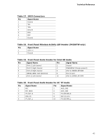
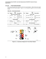
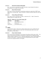
Intel Desktop Board D425KT and Intel Desktop Board D425KTW Technical Product Specification 2.2.2.5 Front Panel USB Headers Figure 12 and Figure 13 are connection diagrams for the front panel USB headers. NOTE • The +5 VDC power on the USB headers is fused. • Use only a front panel USB connector that conforms to the USB 2.0 specification for high-speed USB devices. Figure 12. Connection Diagram for Front Panel USB Header Figure 13. Connection Diagram for Front Panel USB Header with Intel Z-U130 USB Solid-State Drive or Compatible Device Support (D425KTW only) 48
-
 1
1 -
2
-
3
-
4
-
5
-
6
-
7
-
8
-
9
-
10
-
11
-
12
-
13
-
14
-
15
-
16
-
17
-
18
-
19
-
20
-
21
-
22
-
23
-
24
-
25
-
26
-
27
-
28
-
29
-
30
-
31
-
32
-
33
-
34
-
35
-
36
-
37
-
38
-
39
-
40
-
41
-
42
-
 43
43 -
 44
44 -
 45
45 -
 46
46 -
 47
47 -
 48
48 -
 49
49 -
 50
50 -
 51
51 -
 52
52 -
 53
53 -
54
-
55
-
56
-
57
-
58
-
59
-
60
-
61
-
62
-
63
-
64
-
65
-
66
-
67
-
68
-
69
-
70
-
71
-
72
-
73
-
74
-
75
-
76
-
77
-
78
-
79
-
80
-
81
-
82
-
83
-
84
-
85
-
86
-
87
-
88
-
89
 |
 |
Intel Desktop Board D425KT and Intel Desktop Board D425KTW Technical Product
Specification
48
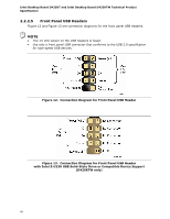
2.2.2.5
Front Panel USB Headers
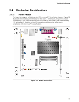
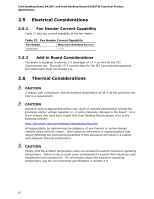
Figure 12 and Figure 13 are connection diagrams for the front panel USB headers.
NOTE
•
The +5 VDC power on the USB headers is fused.
•
Use only a front panel USB connector that conforms to the USB 2.0 specification
for high-speed USB devices.
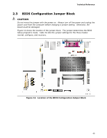
Figure 12.
Connection Diagram for Front Panel USB Header
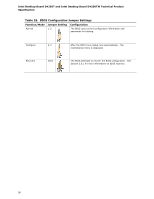
Figure 13.
Connection Diagram for Front Panel USB Header
with Intel Z-U130 USB Solid-State Drive or Compatible Device Support
(D425KTW only)