Intel D525MW Product Guide - Page 28
Installing and Removing Memory - specification
 |
View all Intel D525MW manuals
Add to My Manuals
Save this manual to your list of manuals |
Page 28 highlights
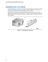
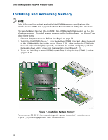
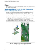
Intel Desktop Board D525MW Product Guide Installing and Removing Memory NOTE To be fully compliant with all applicable Intel SDRAM memory specifications, the boards require DIMMs that support the Serial Presence Detect (SPD) data structure. The Desktop Board has two 204-pin DDR3 SO-DIMM sockets that support up to 4 GB of system memory. To install system memory on the Desktop Board, see Figure 7 and follow these steps: 1. Observe the precautions in "Before You Begin" on page 23. 2. Install the first DIMM (Figure 7, A) in the bottom (DIMM 0) socket. Align the notch in the DIMM with the key in the socket (Figure 7, B), while holding the DIMM with the back edge tilted slightly upwards, insert it in the socket, and gently push the back edge down until it snaps into the retention arms (Figure 7, C). 3. If you are installing a second DIMM, repeat Step 2 using the top (DIMM 1) socket (Figure 7, D). Figure 7. Installing System Memory To remove an SO-DIMM from a socket, gently spread the socket's retention arms (Figure 7, C) to disengage them from the SO-DIMM. 28
-
 1
1 -
2
-
3
-
4
-
5
-
6
-
7
-
8
-
9
-
10
-
11
-
12
-
13
-
14
-
15
-
16
-
17
-
18
-
19
-
20
-
21
-
22
-
 23
23 -
 24
24 -
 25
25 -
 26
26 -
 27
27 -
 28
28 -
 29
29 -
 30
30 -
 31
31 -
 32
32 -
 33
33 -
34
-
35
-
36
-
37
-
38
-
39
-
40
-
41
-
42
-
43
-
44
-
45
-
46
-
47
-
48
-
49
-
50
-
51
-
52
-
53
-
54
-
55
-
56
-
57
-
58
-
59
-
60
-
61
-
62
-
63
-
64
 |
 |