Intel D525MW Product Guide - Page 34
Connecting to the Front Panel Audio Header, Connecting to the S/PDIF Header
 |
View all Intel D525MW manuals
Add to My Manuals
Save this manual to your list of manuals |
Page 34 highlights
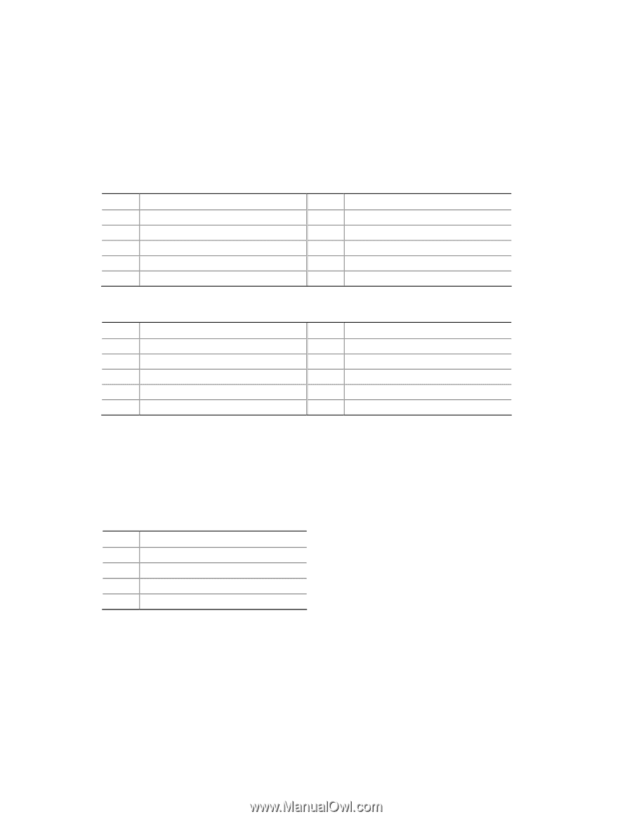
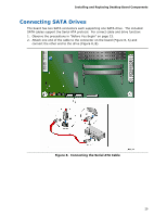
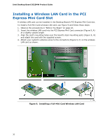
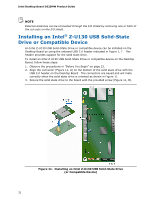
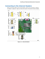
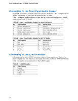
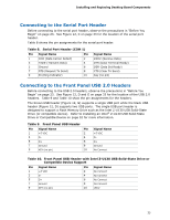
Intel Desktop Board D525MW Product Guide Connecting to the Front Panel Audio Header Figure 12, A shows the location of the front panel audio header. The front panel audio header can be used for both Intel HD Audio and AC '97 Audio. Table 5 shows the pin assignments for the Intel HD Audio and Table 6 shows the pin assignments for AC '97 Audio. Table 5. Front Panel Audio Header for Intel HD Audio Pin Signal Name 1 [Port 1] Left channel 3 [Port 1] Right channel Pin Signal Name 2 Ground 4 PRESENCE# (Dongle present) 5 [Port 2] Right channel 6 [Port 1] SENSE_RETURN 7 SENSE_SEND (Jack detection) 8 Key (no pin) 9 [Port 2] Left channel 10 [Port 2] SENSE_RETURN Table 6. Front Panel Audio Header for AC '97 Audio Pin Signal Name 1 MIC 3 MIC_BIAS 5 FP_OUT_R 7 AUD_5V 9 FP_OUT_L Pin Signal Name 2 AUD_GND 4 AUD_GND 6 FP_RETURN_R 8 KEY (no pin) 10 FP_RETURN_L Connecting to the S/PDIF Header Before connecting to the S/PDIF connector, observe the precautions in "Before You Begin" on page 23. See Figure 12, B on page 33 for the location of the S/PDIF header. Table 7 shows the pin assignments for the S/PDIF header. Table 7. S/PDIF Header Pin Signal Name 1 Ground 2 S/PDIF out 3 Key (no pin) 4 5 VDC 34
-
 1
1 -
2
-
3
-
4
-
5
-
6
-
7
-
8
-
9
-
10
-
11
-
12
-
13
-
14
-
15
-
16
-
17
-
18
-
19
-
20
-
21
-
22
-
23
-
24
-
25
-
26
-
27
-
28
-
 29
29 -
 30
30 -
 31
31 -
 32
32 -
 33
33 -
 34
34 -
 35
35 -
 36
36 -
 37
37 -
 38
38 -
 39
39 -
40
-
41
-
42
-
43
-
44
-
45
-
46
-
47
-
48
-
49
-
50
-
51
-
52
-
53
-
54
-
55
-
56
-
57
-
58
-
59
-
60
-
61
-
62
-
63
-
64
 |
 |