Intel D525MW Product Guide - Page 36
Connecting to the Front Panel Header, Connecting to the Front Panel Wireless Activity LED Header
 |
View all Intel D525MW manuals
Add to My Manuals
Save this manual to your list of manuals |
Page 36 highlights
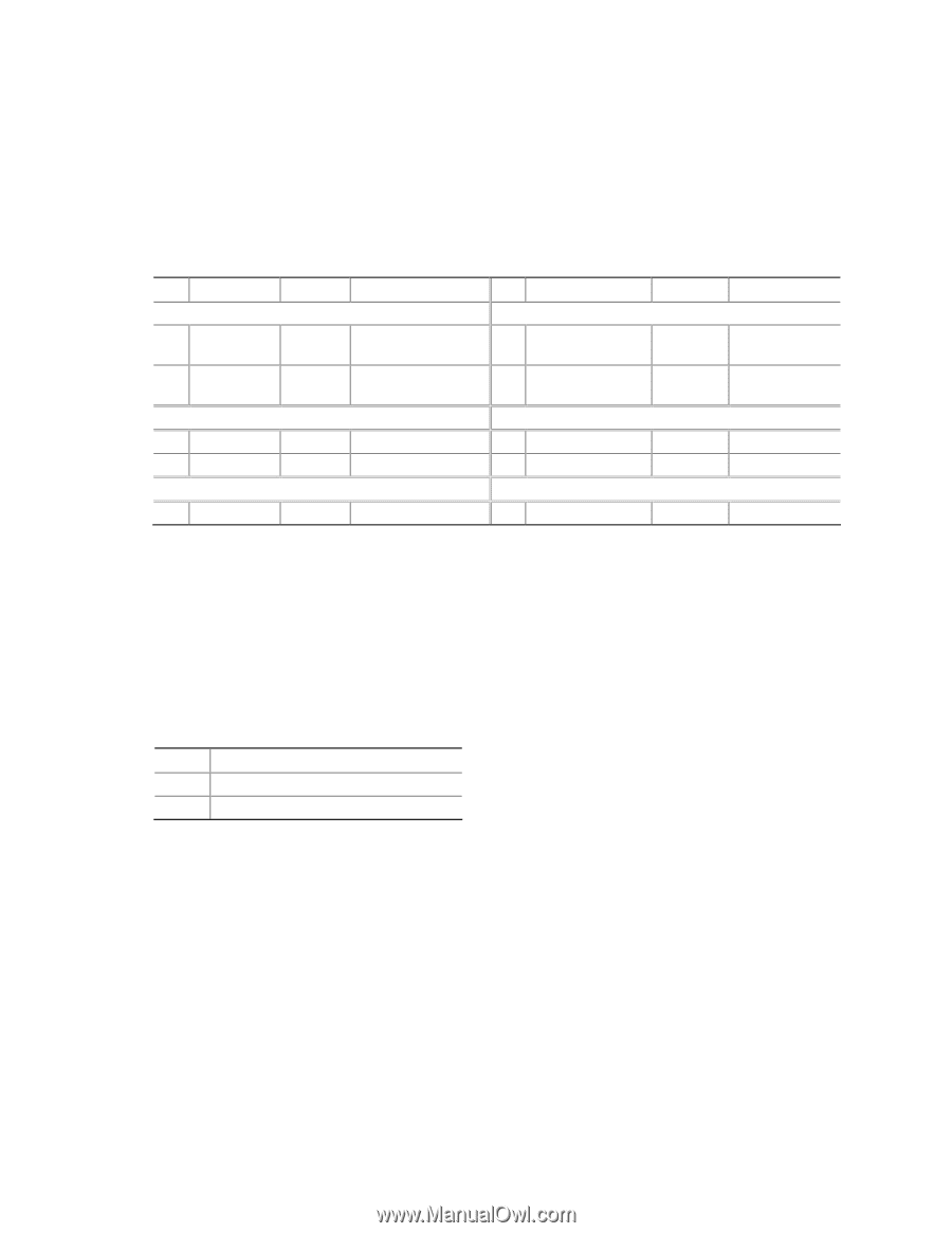
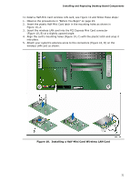
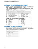
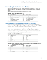
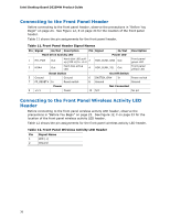
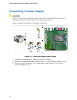
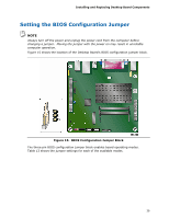
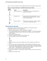
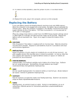
Intel Desktop Board D525MW Product Guide Connecting to the Front Panel Header Before connecting to the front panel header, observe the precautions in "Before You Begin" on page 23. See Figure 12, E on page 33 for the location of the front panel header. Table 11 shows the pin assignments for the front panel header. Table 11. Front Panel Header Signal Names Pin Signal In/Out Description Pin Signal In/Out Hard Drive Activity LED Power LED 1 HD_PWR Out Hard disk LED pullup (330 Ω) to +5 V 2 HDR_BLNK_GRN Out 3 HDA# Out Hard disk active LED 4 HDR_BLNK_YEL Out Description Front panel green LED Front panel yellow LED Reset Switch On/Off Switch 5 Ground 7 FP_RESET# In Ground Reset switch 6 SWITCH_ON# In 8 Ground Power switch Ground Power Not Connected 9 +5 V Power 10 N/C No pin Connecting to the Front Panel Wireless Activity LED Header Before connecting to the front panel wireless activity LED header, observe the precautions in "Before You Begin" on page 23. See Figure 12, F on page 33 for the location of the front panel wireless activity LED header. Table 12 shows the pin assignments for the front panel wireless activity LED header. Table 12. Front Panel Wireless Activity LED Header Pin Signal Name 1 LED (+) 2 Ground 36
-
 1
1 -
2
-
3
-
4
-
5
-
6
-
7
-
8
-
9
-
10
-
11
-
12
-
13
-
14
-
15
-
16
-
17
-
18
-
19
-
20
-
21
-
22
-
23
-
24
-
25
-
26
-
27
-
28
-
29
-
30
-
 31
31 -
 32
32 -
 33
33 -
 34
34 -
 35
35 -
 36
36 -
 37
37 -
 38
38 -
 39
39 -
 40
40 -
 41
41 -
42
-
43
-
44
-
45
-
46
-
47
-
48
-
49
-
50
-
51
-
52
-
53
-
54
-
55
-
56
-
57
-
58
-
59
-
60
-
61
-
62
-
63
-
64
 |
 |