Intel D845GLLY D845GL_Boards_SpecUpdate09 - Page 20
CAUTION, INTEGRATOR, S NOTE, Table 18., Front Panel Audio Connector/Jumper Block - bios recovery
 |
View all Intel D845GLLY manuals
Add to My Manuals
Save this manual to your list of manuals |
Page 20 highlights
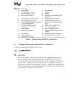
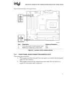
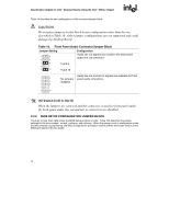
Specification Update for Intel Desktop Boards Using the Intel 845GL Chipset Table 18 describes the two configurations of this connector/jumper block. CAUTION Do not place jumpers on this block in any configuration other than the one described in Table 18. Other jumper configurations are not supported and could damage the Desktop Board. Table 18. Front Panel Audio Connector/Jumper Block Jumper Setting 1 2 3 4 5 6 7 9 10 5 and 6 9 and 10 Configuration Audio line out signals are routed to the back panel audio line out connector. 1 2 3 4 5 6 7 9 10 No jumpers installed Audio line out and mic in signals are available for front panel audio connectors. # INTEGRATOR'S NOTE When the jumpers are removed and this connector is used for front panel audio, the back panel audio line out and mic in connectors are disabled. 2.3.2 BIOS SETUP CONFIGURATION JUMPER BLOCK The 3-pin jumper block determines the BIOS Setup program's mode. Table 18A describes the jumper settings for the three modes: normal, configure, and recovery. When the jumper is set to configuration mode and the computer is powered-up, the BIOS compares the processor version and the microcode version in the BIOS and reports if the two match. 14
-
 1
1 -
2
-
3
-
4
-
5
-
6
-
7
-
8
-
9
-
10
-
11
-
12
-
13
-
14
-
 15
15 -
 16
16 -
 17
17 -
 18
18 -
 19
19 -
 20
20 -
 21
21 -
 22
22 -
 23
23 -
 24
24 -
 25
25 -
26
-
27
-
28
 |
 |
