Intel D845GLLY D845GL_Boards_SpecUpdate09 - Page 25
Specification Clarifications
 |
View all Intel D845GLLY manuals
Add to My Manuals
Save this manual to your list of manuals |
Page 25 highlights
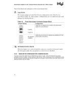
Specification Update for Intel Desktop Boards Using the Intel 845GL Chipset SPECIFICATION CLARIFICATIONS The Specification Clarifications listed in this section apply to the Technical Product Specification for Intel Desktop Boards using the Intel 845GL Chipset (Order Number A90788). All Specification Clarifications will be incorporated into a future version of that specification. 1. Change to Description of Table 4A, Section 2.2.2.2, Audio, Power, and Hardware Control Connectors Table 4A will be added to Section 2.2.2.2, Audio, Power, and Hardware Control Connectors as follows: Table 4A. Front Panel Audio Connector Pin Signal Name Pin 1 MIC_IN 2 3 MIC_BIAS 4 5 RIGHT_OUT 6 7 Not Connected 8 9 LEFT_OUT 10 Signal Name Ground +5 V RIGHT_IN Key LEFT_IN 2. Clarification of SMBus Routing Section 2.8.2.1 will change in its entirety as follows: 2.8.2.1 Expansion Slots The Desktop Board has four PCI rev 2.2 compliant local bus slots. The SMBus is routed to PCI bus connector 2. ✏ NOTE The SMBus routing to the PCI bus connectors does not conform to the PCI Engineering Change Notice (ECN) "Addition of the SMBus to the PCI Connector ECN", dated October 5th, 2000. The ECN specifies that SMBus signals must be routed to all PCI bus connectors. On this board, SMBus signals are routed to PCI bus connector 2 only. Add-in cards that implement PCI bus connector pins A40 and A41 for any purpose other than SMBCLK (SMBus clock) and SMBDAT (SMBus data) should not be installed in PCI bus connector 2. 19
-
 1
1 -
2
-
3
-
4
-
5
-
6
-
7
-
8
-
9
-
10
-
11
-
12
-
13
-
14
-
15
-
16
-
17
-
18
-
19
-
 20
20 -
 21
21 -
 22
22 -
 23
23 -
 24
24 -
 25
25 -
 26
26 -
 27
27 -
 28
28
 |
 |
