Intel D845GVAD2 Product Guide
Intel D845GVAD2 - P4 Socket 478 ATX Motherboard Manual
 |
UPC - 735858157902
View all Intel D845GVAD2 manuals
Add to My Manuals
Save this manual to your list of manuals |
Intel D845GVAD2 manual content summary:
- Intel D845GVAD2 | Product Guide - Page 1
Intel® Desktop Board D845GVAD2 Product Guide Order Number: C14171-001 - Intel D845GVAD2 | Product Guide - Page 2
of the Intel® Desktop Board D845GVAD2 Product Guide. Date August 2002 If an FCC declaration of conformity marking is present on the board, the energy and, if not installed and used in accordance with the instructions, may cause harmful interference to radio communications. However, there is - Intel D845GVAD2 | Product Guide - Page 3
Desktop Board Features Desktop Board Components 9 Processor ...10 Main Memory ...11 Intel® 845GV Chipset ...11 Intel® 82845GV Graphics and Memory Controller Hub (GMCH 12 Intel® 82801DB I/O Controller Hub (ICH4 12 Firmware Hub (FWH 12 Input/Output (I/O) Controller 12 Integrated Graphics...13 LAN - Intel D845GVAD2 | Product Guide - Page 4
Intel Desktop Board D845GVAD2 Product Guide Installing and Removing Memory 24 Installing DIMMs ...24 Removing DIMMs ...25 Connecting the IDE Cable 25 Connecting the Front Panel Header 27 Installing a Front Panel Audio Solution (Optional 27 Installing a Front Panel USB Solution 27 Setting the - Intel D845GVAD2 | Product Guide - Page 5
Heat Sink Cable to the Processor Fan Connector ........23 7. Installing a Memory Module 24 8. Connecting the IDE Cable 26 9. Location of the BIOS Configuration Jumper Block 28 10. Removing the Battery from the Desktop Board 31 11. Back Panel Connectors 60 12. Audio Connectors ...61 13. Power - Intel D845GVAD2 | Product Guide - Page 6
Intel Desktop Board D845GVAD2 Product Guide Tables 1. Feature Summary ...7 2. Processors Supported by the Desktop Board 10 3. RJ-45 LAN Connector LEDs 14 4. Jumper Settings for the BIOS Setup Program Modes (J9H2 28 5. BIOS Setup Program Menu Bar 37 6. BIOS Setup Program Function Keys 38 7. - Intel D845GVAD2 | Product Guide - Page 7
® Desktop Board D845GVAD2. Table 1. Feature Summary Form Factor Processor Memory Chipset I/O Control LAN (optional) Graphics Audio Expansion Capabilities • microATX at 9.2 inches by 8.2 inches Support for: • 533 MHz or 400 MHz front side bus (FSB) Intel® Pentium® 4 processor in an mPGA_478 socket - Intel D845GVAD2 | Product Guide - Page 8
Available PC) • Wake on USB, PCI, RS-232, LAN, and front panel ✏ NOTE For information about Intel desktop boards, including the Technical Product Specification (TPS), BIOS updates, and device drivers, go to the Intel World Wide Web site at: http://support.intel.com/support/motherboards/desktop/ 8 - Intel D845GVAD2 | Product Guide - Page 9
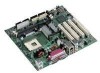
components on Desktop Board D845GVAD2. A B CD E F G H I Z J Y K X W L V SRQ UT PO NM OM14568 A Audio codec N B Front panel audio header (optional) O C Auxiliary line-in connector (ATAPI) P D CD-ROM connector (ATAPI) Q E Back panel connectors R F 12 V processor core voltage - Intel D845GVAD2 | Product Guide - Page 10
the latest information on processor support for Desktop Board D845GVAD2, refer to the Intel World Wide Web site at: http://support.intel.com/support/motherboards/desktop/ For instructions on installing or upgrading the processor, see Chapter 2 on page 19. Desktop Board D845GVAD2 requires an ATX12V - Intel D845GVAD2 | Product Guide - Page 11
the PC SDRAM Specification (memory component specific), the PC Unbuffered DIMM Specification. To view or download these specifications, refer to this Intel World Wide Web site: http://www.intel.com/technology/memory/pcsdram/spec/ Desktop Board D845GVAD2 supports system memory as defined below - Intel D845GVAD2 | Product Guide - Page 12
Intel Desktop Board D845GVAD2 Product Guide Intel® 82845GV Graphics and Memory Controller Hub (GMCH) The GMCH provides the processor, system memory, and hub interfaces in the Intel 845GV chipset platform. Features on Desktop Board D845GVAD2 include: • Single processor support with 533 MHz/400 MHz - Intel D845GVAD2 | Product Guide - Page 13
RJ-45 connector with status indicator LEDs • Programmable transit threshold • Configurable EEPROM that contains the MAC address LAN Subsystem Software For LAN software and drivers, refer to the D845GVAD2 link on Intel's World Wide Web site at: http://support.intel.com/support/motherboards/desktop 13 - Intel D845GVAD2 | Product Guide - Page 14
Intel Desktop Board D845GVAD2 Product Guide RJ-45 LAN Connector LEDs Two LEDs are built into the RJ-45 LAN connector. Table 3 describes the LED states when the Intel desktop board is powered up and the LAN subsystem is operating. Table 3. RJ-45 LAN Connector LEDs LED Color Green Yellow LED State - Intel D845GVAD2 | Product Guide - Page 15
Slots Desktop Board D845GVAD2 has four PCI bus add-in card connectors. BIOS The BIOS provides the Power-On Self-Test (POST), the BIOS Setup program, the PCI and IDE auto-configuration utilities, and the video BIOS. The BIOS is stored in the Firmware Hub. The BIOS can be updated by following - Intel D845GVAD2 | Product Guide - Page 16
use of ACPI with Desktop Board D845GVAD2 requires an operating system that provides full ACPI support. Suspend to RAM (Instantly Available PC state. The desktop board's standby power indicator, shown in Figure 2, is lit when there is standby power to the system. This includes the memory modules and - Intel D845GVAD2 | Product Guide - Page 17
PS/2 keyboard/mouse • PME# wake up support Power Connectors Desktop Board D845GVAD2 has two power connectors. See Figure 13 on page 62 for the location of the power connectors. Fan Connectors Desktop Board D845GVAD2 has two chassis fan connectors and one processor fan connector. See Figure 13 on - Intel D845GVAD2 | Product Guide - Page 18
the values in CMOS RAM and the clock current when the computer is turned off. See Chapter 2 starting on page 19 for instructions on how to replace the battery. Real-Time Clock Desktop Board D845GVAD2 has a time-of-day clock and 100-year calendar. A battery on the Intel desktop board keeps the clock - Intel D845GVAD2 | Product Guide - Page 19
the desktop board • Install and remove a processor • Install and remove memory • Connect the IDE cable • Connect the front panel header (not included) • Install the front panel audio solution (not included) • Install the front panel USB solution (not included) • Set the BIOS configuration jumper - Intel D845GVAD2 | Product Guide - Page 20
Intel Desktop Board D845GVAD2 Product Guide Installing the I/O Shield The Intel desktop board comes with an I/O shield. When installed in the chassis, the shield blocks radio frequency transmissions, protects internal components from dust and foreign objects, and promotes - Intel D845GVAD2 | Product Guide - Page 21
Installing and Replacing Desktop Board Components Installing and Removing the Desktop Board Refer to your chassis manual for instructions on installing and removing the desktop board. WARNING Only qualified technical personnel should do this procedure. Disconnect the computer from its power source - Intel D845GVAD2 | Product Guide - Page 22
Sink Desktop Board D845GVAD2 has an integrated processor fan heat sink retention mechanism (RM). For instructions on how to install the processor fan heat sink to the integrated processor fan heat sink RM, refer to the boxed processor manual or the Intel World Wide Web site at: http://support.intel - Intel D845GVAD2 | Product Guide - Page 23
the Processor Fan Heat Sink Cable to the Processor Fan Connector Removing a Processor For instruction on how to remove the processor fan heat sink, refer to the processor installation manual or the Intel World Wide Web site at: http://support.intel.com/support/processors/pentium4/intnotes478 - Intel D845GVAD2 | Product Guide - Page 24
PC Serial Presence Detect Specification at: http://www.intel.com/technology/memory/pcsdram/spec/ ✏ NOTE Remove the PCI bus connector 1 card before installing or upgrading memory to avoid interference with the memory retention mechanism. Desktop Board D845GVAD2 has two DIMM sockets arranged as DIMM - Intel D845GVAD2 | Product Guide - Page 25
or disconnected to reach the DIMM sockets. 8. Replace the computer's cover and reconnect the AC power cord. Connecting the IDE Cable The Intel® boxed desktop board package includes an IDE cable. The cable connects two drives to the desktop board. The cable supports ATA-66 and ATA-100 transfer - Intel D845GVAD2 | Product Guide - Page 26
Intel Desktop Board D845GVAD2 Product Guide For correct function of the cable: • Attach the cable end with the single connector to the Intel desktop board (see Figure 8, A). • Attach the cable end with the two closely spaced connectors to the drives (see Figure 8, B). A OM14571 B Figure 8. - Intel D845GVAD2 | Product Guide - Page 27
Installing and Replacing Desktop Board Components Connecting the Front Panel Header Before connecting the front panel header, observe the precautions in "Before You Begin" on page 19. Refer to Table 31 on page 65 for pin assignments. Installing a Front Panel Audio Solution (Optional) To install the - Intel D845GVAD2 | Product Guide - Page 28
Intel Desktop Board D845GVAD2 Product Guide Setting the BIOS Configuration Jumper Block Figure 9 shows the location of the BIOS configuration jumper block (J9H2). 31 J9H2 OM14572 Figure 9. Location of the BIOS Configuration Jumper Block The three-pin BIOS jumper block enables all board - Intel D845GVAD2 | Product Guide - Page 29
Desktop Board Components Clearing Passwords This procedure assumes that the board displays the maintenance menu. 8. Use the arrow keys to select Clear Passwords. Press and Setup displays memory. When the computer is not plugged into a wall socket BIOS Setup program settings stored in CMOS RAM - Intel D845GVAD2 | Product Guide - Page 30
Intel Desktop Board D845GVAD2 Product Guide FORHOLDSREGEL Eksplosionsfare, hvis batteriet erstattes med et batteri af en forkert type. Batterier bør om muligt genbruges. Bortskaffelse af brugte batterier bør foregå i overensstemmelse med gældende miljø - Intel D845GVAD2 | Product Guide - Page 31
cover. 4. Locate the battery on the board (see Figure 10). 5. Note the orientation of the "+" and "-" on the battery. 6. Install the new battery in the connector, orienting the "+" and "-" correctly. 7. Replace the computer cover. OM13688 Figure 10. Removing the Battery from the Desktop Board 31 - Intel D845GVAD2 | Product Guide - Page 32
Intel Desktop Board D845GVAD2 Product Guide 32 - Intel D845GVAD2 | Product Guide - Page 33
wizards. To update the BIOS with the Intel Express BIOS Update utility: 1. Go to the Intel World Wide Web site: http://support.intel.com/support/motherboards/desktop/ 2. Navigate to the D845GVAD2 page and click the Express BIOS Update utility file for the D845GVAD2 board's BIOS. 3. Download the file - Intel D845GVAD2 | Product Guide - Page 34
Intel Desktop Board D845GVAD2 Product Guide ✏ NOTE Review the instructions distributed with the update utility before attempting a BIOS update. The Intel Flash Memory Update Utility allows you to: • Update the BIOS in flash memory • Update the language section of the BIOS Updating the BIOS CAUTION - Intel D845GVAD2 | Product Guide - Page 35
Updating the BIOS 6. Listen to the speaker: • Upon applying power, drive A will begin to show activity. In about a minute, two beeps are heard and drive A activity ceases (temporarily) indicating the successful recovery of the BIOS core. Drive A activity will begin again followed by two more beeps - Intel D845GVAD2 | Product Guide - Page 36
Intel Desktop Board D845GVAD2 Product Guide 36 - Intel D845GVAD2 | Product Guide - Page 37
section may not show the latest settings. For the latest BIOS settings, refer to the Intel Desktop Board D845GVAD2 Technical Product Specification or the Intel World Wide Web site: http://support.intel.com/support/motherboards/desktop ✏ NOTE For reference purposes, you should write down the current - Intel D845GVAD2 | Product Guide - Page 38
Intel Desktop Board D845GVAD2 Product Guide Table 6 shows the function keys available for menu screens. Table 6. BIOS Setup Program Function Keys BIOS Setup Program Function Key or or Description Selects a different menu screen Moves cursor up or down - Intel D845GVAD2 | Product Guide - Page 39
of the BIOS. Displays processor type. Displays processor speed. Displays the system bus speed. Dislays the system memory speed. Displays the size of second-level cache and whether it is ECC-capable. Displays the total amount of RAM. Displays the amount and type of RAM in the memory banks. Selects - Intel D845GVAD2 | Product Guide - Page 40
Intel Desktop Board D845GVAD2 Product Guide Advanced Menu Maintenance Main Advanced Security Power Boot Exit PCI Configuration Boot Configuration Peripheral Configuration IDE Configuration Diskette Configuration Event Log Configuration Video Configuration USB Configuration Chipset - Intel D845GVAD2 | Product Guide - Page 41
Using the BIOS Setup Program PCI Configuration Submenu Maintenance Main Advanced Security Power Boot Exit PCI Configuration Boot Configuration Peripheral Configuration IDE Configuration Diskette Configuration Event Log Configuration Video Configuration USB Configuration Chipset Configuration - Intel D845GVAD2 | Product Guide - Page 42
Intel Desktop Board D845GVAD2 Product Guide Boot Configuration Submenu Maintenance Main Advanced Security Power Boot Exit PCI Configuration Boot Configuration Peripheral Configuration IDE Configuration Diskette Configuration Event Log Configuration Video Configuration USB Configuration - Intel D845GVAD2 | Product Guide - Page 43
for serial port A, if serial port A is Enabled. Configures serial port B. Auto assigns the first free COM port, normally COM1, the address 3F8h, and the interrupt IRQ4. An * (asterisk) displayed next to an address indicates a conflict with another device. Specifies the base I/O address for serial - Intel D845GVAD2 | Product Guide - Page 44
Intel Desktop Board D845GVAD2 Product Guide Table 12. Peripheral Configuration Submenu (continued) Feature Parallel Port Mode Options when ECP mode is selected) Audio • Disabled • Enabled (default) LAN Device (This feature is present only when there is onboard LAN) • Disabled • Enabled ( - Intel D845GVAD2 | Product Guide - Page 45
transaction as a master. Specifies the hard disk drive pre-delay. Causes the BIOS to insert a delay before attempting to detect IDE drives in the system. Reports type of connected IDE device. When selected, displays the Primary IDE Master submenu. Reports type of connected IDE device. When selected - Intel D845GVAD2 | Product Guide - Page 46
Intel Desktop Board D845GVAD2 Product Guide Primary/Secondary IDE Master/Slave Submenus Maintenance Main Advanced Security PCI Configuration Boot Configuration Peripheral Configuration IDE Configuration Diskette Configuration Event Log Configuration Video Configuration USB Configuration - Intel D845GVAD2 | Product Guide - Page 47
Using the BIOS Setup Program Table 14. Primary/Secondary IDE Master/Slave Submenus Description Specifies the PIO mode. Specifies Single Word, Multi Word, or Ultra DMA mode for the drive. Displays the type of cable connected to the IDE interface: 40-conductor or 80-conductor (for ATA-66/100 devices - Intel D845GVAD2 | Product Guide - Page 48
Intel Desktop Board D845GVAD2 Product Guide Diskette Configuration Submenu Maintenance Main Advanced Security Power Boot Exit PCI Configuration Boot Configuration Peripheral Configuration IDE Configuration Diskette Configuration Event Log Configuration Video Configuration USB Configuration - Intel D845GVAD2 | Product Guide - Page 49
Using the BIOS Setup Program Event Log Configuration Submenu Maintenance Main Advanced Security Power Boot Exit PCI Configuration Boot Configuration Peripheral Configuration IDE Configuration Floppy Configuration Event Log Configuration Video Configuration USB Configuration Chipset - Intel D845GVAD2 | Product Guide - Page 50
Intel Desktop Board D845GVAD2 Product Guide Video Configuration Submenu Maintenance Main Advanced Security Power Boot Exit PCI Configuration Boot Configuration Peripheral Configuration IDE Configuration Diskette Configuration Event Log Configuration Video Configuration USB Configuration - Intel D845GVAD2 | Product Guide - Page 51
18 is used to configure USB features. Table 18. USB Configuration Submenu Feature High Speed USB Legacy USB Support Options • Disabled • Enabled (default) • Disabled • Enabled (default) Description Disable this option when a USB 2.0 driver is not available. Enables support for legacy USB. 51 - Intel D845GVAD2 | Product Guide - Page 52
Intel Desktop Board D845GVAD2 Product Guide Chipset Configuration Submenu Maintenance Main Advanced Security Power Boot Exit PCI Configuration Boot Configuration Peripheral Configuration IDE Configuration Diskette Configuration Event Log Configuration Video Configuration USB Configuration - Intel D845GVAD2 | Product Guide - Page 53
. Selects the number of clock cycles required to address a column in memory. Selects the number of clock cycles between addressing a row and addressing (default) Password can be up to seven alphanumeric characters. Sets BIOS Setup Utility access rights for user level. Specifies the user password - Intel D845GVAD2 | Product Guide - Page 54
Intel Desktop Board D845GVAD2 Product Guide Power Menu Maintenance Main Advanced Security Power Boot Exit The menu shown in Table 21 is used to set power management features. Table 21. Power Menu Feature Options Description ACPI [Enter] When selected, displays Wake on LAN from S5 - Intel D845GVAD2 | Product Guide - Page 55
Boot Menu Feature Silent Boot Options • Disabled • Enabled (default) Description Disabled displays normal POST messages. Enabled displays OEM logo instead of POST messages. Intel Rapid BIOS Boot Scan User Flash Area PXE Boot to LAN USB Boot Boot Device Priority Hard Disk Drives Removable Devices - Intel D845GVAD2 | Product Guide - Page 56
Intel Desktop Board D845GVAD2 Product Guide Boot Device Priority Submenu Maintenance Main Advanced Security Power Boot Exit least one boot device of this type is installed. This list will display up to twelve hard disk drives, the maximum number of hard disk drives supported by the BIOS. 56 - Intel D845GVAD2 | Product Guide - Page 57
appears only if at least one boot device of this type is installed. This list will display up to four removable devices, the maximum number of removable devices supported by the BIOS. ATAPI CD-ROM Drives Maintenance Main Advanced Security Power Boot Exit Boot Device Priority Hard Disk - Intel D845GVAD2 | Product Guide - Page 58
Intel Desktop Board D845GVAD2 Product Guide Exit Menu Maintenance Main Advanced Security Power Boot Exit The menu shown in Table 28 is used to exit the BIOS Setup program, saving changes, and loading and saving defaults. Table 28. Exit Menu Feature Description Exit Saving Changes Exits - Intel D845GVAD2 | Product Guide - Page 59
connectors can be divided into three groups: • Back panel connectors • Midboard connectors - Audio connectors - Power and hardware connectors - Add-in board and peripheral interface connectors • Front panel headers CAUTION Many of the midboard and front panel connectors provide operating voltage - Intel D845GVAD2 | Product Guide - Page 60
Intel Desktop Board D845GVAD2 Product Guide Back Panel Connectors Figure 11 shows the back panel connectors. A C F B Item A B C D E F G H I J K D E Description PS/2 mouse port PS/2 keyboard port Parallel port Serial port A VGA port RJ-45 (optional) USB 2.0 port USB 2.0 port Mic in Audio line - Intel D845GVAD2 | Product Guide - Page 61
) Auxiliary line in (ATAPI) CD-ROM (ATAPI) Black Light grey Black Figure 12. Audio Connectors OM14573 Table 29 shows the pin assignments for the optional front panel audio header. Table 29. Front Panel Audio Header Signal Names (J8A1) Pin Signal Name 1 AUD-MIC 3 AUD-MIC-BIAS 5 AUD - Intel D845GVAD2 | Product Guide - Page 62
12V compliant power supply to function according to desktop board specifications. The desktop board has two ATX12V or SFX_12V compliant power supply connectors that are needed to provide extra power to the Intel 845GV chipset and Pentium 4 processor. Figure 13 shows the power and hardware connectors - Intel D845GVAD2 | Product Guide - Page 63
Add-In Card and Peripheral Interface Connectors Figure 14 shows the add-in card and peripheral interface connectors. A BCD Technical Reference 2 40 1 39 2 40 2 34 1 39 1 33 G F Item A B C D Description PCI bus connector 4 PCI bus connector 3 PCI bus connector 2 (SMBus routed) PCI bus - Intel D845GVAD2 | Product Guide - Page 64
Intel Desktop Board D845GVAD2 Product Guide Front Panel Headers Figure 15 shows the location of the front panel headers. 1 2 3 4 5 6 7 9 10 A 1 2 3 4 5 6 7 8 10 B 1 2 3 4 5 6 7 8 9 C 1 2 Item A B C D D OM14576 Description Front panel audio (optional) (see Table 29 - Intel D845GVAD2 | Product Guide - Page 65
Technical Reference Table 30 shows the pin assignments for the front panel USB 2.0 header. Table 30. Front Panel USB 2.0 Header (J9F2) Pin Signal name Pin 1 VREG_FP_WSBPWR0 2 3 USB_FPP0- 4 5 USB_FPP0+ 6 7 Ground 8 9 Key 10 Note: USB ports may be assigned as needed. Signal name - Intel D845GVAD2 | Product Guide - Page 66
Intel Desktop Board D845GVAD2 Product Guide Desktop Board Resources Memory Map Table 32. System Memory Map Address Range (decimal) 1024 K - 2097152 K 960 K - 1024 K 896 K - 960 K 800 K - 896 K Address Range (hex) 100000 - 7FFFFFF F0000 - FFFFF E0000 - EFFFF C8000 - DFFFF 640 K - 800 K - Intel D845GVAD2 | Product Guide - Page 67
Interrupts Table 34. Interrupts IRQ System Resource NMI I/O channel check 0 Reserved, interval timer 1 Reserved, keyboard buffer full 2 Reserved, cascade interrupt from slave PIC 3 COM2* 4 COM1* 5 LPT2 (Plug & Play option) / ** 6 Diskette drive controller 7 LPT1* 8 Real time - Intel D845GVAD2 | Product Guide - Page 68
Intel Desktop Board D845GVAD2 Product Guide 68 - Intel D845GVAD2 | Product Guide - Page 69
Desktop Board D845GVAD2 reports POST errors in two ways: • By sounding a beep code • By displaying an error message on the monitor BIOS Beep Codes The BIOS beep codes are listed in Table 35. The BIOS also issues a beep code (one long tone followed by two short tones) during POST if the video - Intel D845GVAD2 | Product Guide - Page 70
Intel Desktop Board D845GVAD2 Product Guide BIOS Error Messages When a recoverable error occurs during the POST, the BIOS displays an error message describing the problem. Table 36. BIOS Error Messages Error Message Explanation GA20 Error An error occurred with Gate-A20 when switching to - Intel D845GVAD2 | Product Guide - Page 71
Error Messages and Indicators Table 36. BIOS Error Messages (continued) Error Message Memory Size Decreased Memory Size Increased Memory Size Changed No Boot Device Available Off Board Parity Error On Board Parity Error Parity Error NVRAM / CMOS / PASSWORD cleared by Jumper Pressed - Intel D845GVAD2 | Product Guide - Page 72
Intel Desktop Board D845GVAD2 Product Guide 72 - Intel D845GVAD2 | Product Guide - Page 73
compatibility (EMC) regulations, and product certification markings for Desktop Board D845GVAD2. • Instructions and precautions for integrators who are installing the Intel desktop board in a chassis. Safety Regulations Desktop Board D845GVAD2 complies with the safety regulations stated in Table - Intel D845GVAD2 | Product Guide - Page 74
Intel Desktop Board D845GVAD2 Product Guide Product Certification Markings Desktop Board D845GVAD2 has the following product certification markings: • UL joint US/Canada Recognized Component mark: consists of small c followed by a stylized backward UR and followed by a small - Intel D845GVAD2 | Product Guide - Page 75
and test the desktop board, observe all warnings and cautions in the installation instructions. To avoid injury, be careful of: • Sharp pins on connectors • Sharp pins on printed circuit assemblies • Rough edges and sharp corners on the chassis • Hot components (like processors, voltage regulators - Intel D845GVAD2 | Product Guide - Page 76
Intel Desktop Board D845GVAD2 Product Guide Chassis and Component Certifications Ensure that the chassis and certain used batteries according to the manufacturer's instructions. Use Only for Intended Applications All Intel desktop processor boards are evaluated as Information Technology Equipment
-
 1
1 -
 2
2 -
 3
3 -
 4
4 -
 5
5 -
 6
6 -
 7
7 -
8
-
9
-
10
-
11
-
12
-
13
-
14
-
15
-
16
-
17
-
18
-
19
-
20
-
21
-
22
-
23
-
24
-
25
-
26
-
27
-
28
-
29
-
30
-
31
-
32
-
33
-
34
-
35
-
36
-
37
-
38
-
39
-
40
-
41
-
42
-
43
-
44
-
45
-
46
-
47
-
48
-
49
-
50
-
51
-
52
-
53
-
54
-
55
-
56
-
57
-
58
-
59
-
60
-
61
-
62
-
63
-
64
-
65
-
66
-
67
-
68
-
69
-
70
-
71
-
72
-
73
-
74
-
75
-
76
 |
 |

Intel
®
Desktop Board
D845GVAD2
Product Guide
Order Number:
C14171-001