Intel D845GVAD2 Product Guide - Page 25
Removing DIMMs, Connecting the IDE Cable
 |
UPC - 735858157902
View all Intel D845GVAD2 manuals
Add to My Manuals
Save this manual to your list of manuals |
Page 25 highlights
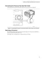
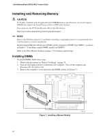
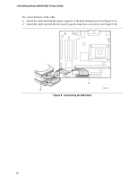
Installing and Replacing Desktop Board Components 4. Make sure the clips at either end of the DIMM socket(s) are pushed outward to the open position. 5. Position the DIMM above the socket. Align the two small notches in the bottom edge of the DIMM with the keys in the socket (see inset in Figure 7). 6. Insert the bottom edge of the DIMM into the socket. 7. When the DIMM is inserted, push down on the top edge of the DIMM until the retaining clips snap into place. Make sure the clips are firmly in place. 8. Replace the computer's cover and reconnect the AC power cord. Removing DIMMs To remove a memory module, follow these steps: 1. Observe the precautions in "Before You Begin" on page 19. 2. Turn off all peripheral devices connected to the computer. Turn off the computer. 3. Remove the AC power cord from the computer. 4. Remove the computer's cover. 5. Gently spread the retaining clips at each end of the DIMM socket. The DIMM pops out of the socket. 6. Hold the DIMM by the edges, lift it away from the socket, and store it in an anti-static package. 7. Reinstall and reconnect any parts you removed or disconnected to reach the DIMM sockets. 8. Replace the computer's cover and reconnect the AC power cord. Connecting the IDE Cable The Intel® boxed desktop board package includes an IDE cable. The cable connects two drives to the desktop board. The cable supports ATA-66 and ATA-100 transfer protocols and is backward compatible with drives using slower IDE transfer protocols. Figure 8 shows the correct installation of the cable. ✏ NOTE ATA-66/100 compatible cables are backward compatible with drives using slower IDE transfer protocols. If an ATA-66/100 disk drive and a disk drive using any other IDE transfer protocol are attached to the same cable, the maximum transfer rate between the drives may be reduced to that of the slowest drive. ✏ NOTE Do not connect an ATA device as a slave on the same IDE cable as an ATAPI master device. For example, do not connect an ATA hard drive as a slave to an ATAPI CD-ROM drive. 25
-
 1
1 -
2
-
3
-
4
-
5
-
6
-
7
-
8
-
9
-
10
-
11
-
12
-
13
-
14
-
15
-
16
-
17
-
18
-
19
-
 20
20 -
 21
21 -
 22
22 -
 23
23 -
 24
24 -
 25
25 -
 26
26 -
 27
27 -
 28
28 -
 29
29 -
 30
30 -
31
-
32
-
33
-
34
-
35
-
36
-
37
-
38
-
39
-
40
-
41
-
42
-
43
-
44
-
45
-
46
-
47
-
48
-
49
-
50
-
51
-
52
-
53
-
54
-
55
-
56
-
57
-
58
-
59
-
60
-
61
-
62
-
63
-
64
-
65
-
66
-
67
-
68
-
69
-
70
-
71
-
72
-
73
-
74
-
75
-
76
 |
 |