Contents
v
Power and Hardware Connectors
......................................................................
62
Add-In Card and Peripheral Interface Connectors
..............................................
63
Front Panel Headers
..................................................................................................
64
Desktop Board Resources
...................................................................................................
66
Memory Map
..............................................................................................................
66
DMA Channels
...........................................................................................................
66
Interrupts
....................................................................................................................
67
A
Error Messages and Indicators
BIOS Beep Codes
...............................................................................................................
69
BIOS Error Messages
.........................................................................................................
70
B
Regulatory Compliance
Safety Regulations
..............................................................................................................
73
EMC Regulations
................................................................................................................
73
Product Certification Markings
.............................................................................................
74
Installation Instructions
........................................................................................................
75
Ensure Electromagnetic Compatibility (EMC) Compliance
.........................................
75
Chassis and Component Certifications
.......................................................................
76
Prevent Power Supply Overload
.................................................................................
76
Place Battery Marking
................................................................................................
76
Use Only for Intended Applications
.............................................................................
76
Figures
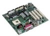
1.
Desktop Board Components
..........................................................................................
9
2.
Location of the Standby Power Indicator
.......................................................................
16
3.
Installing the I/O Shield
.................................................................................................
20
4.
Desktop Board Mounting Holes
....................................................................................
21
5.
Installing a Processor
....................................................................................................
22
6.
Connecting the Processor Fan Heat Sink Cable to the Processor Fan Connector
........
23
7.
Installing a Memory Module
..........................................................................................
24
8.
Connecting the IDE Cable
.............................................................................................
26
9.
Location of the BIOS Configuration Jumper Block
........................................................
28
10. Removing the Battery from the Desktop Board
.............................................................
31
11. Back Panel Connectors
................................................................................................
60
12. Audio Connectors
.........................................................................................................
61
13
.
Power and Hardware Control Connectors
.....................................................................
62
14. Add-in Card and Peripheral Interface Connectors
.........................................................
63
15. Front Panel Headers
.....................................................................................................
64
 1
1 2
2 3
3 4
4 5
5 6
6 7
7 8
8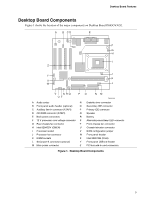 9
9 10
10 11
11