Intel D945GNT Product Specification - Page 58
Component-side Connectors
 |
View all Intel D945GNT manuals
Add to My Manuals
Save this manual to your list of manuals |
Page 58 highlights
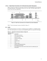
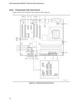
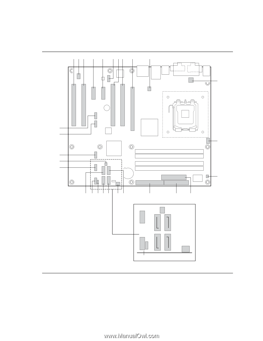
Intel Desktop Board D945GNT Technical Product Specification 2.8.2 Component-side Connectors Figure 20 shows the locations of the component-side connectors. A B C D E F GH I J 4 12 1 9 10 1 3 12 K 34 BB AA 10 21 10 21 12 Z 10 Y X 4 1 L 24 2 23 1 M 1 2 40 2 34 1 39 1 33 W V UTS RQ P ON 12 1 1 10 9 1 21 1 1 11 3 Figure 20. Component-side Connectors OM17745 58
-
 1
1 -
2
-
3
-
4
-
5
-
6
-
7
-
8
-
9
-
10
-
11
-
12
-
13
-
14
-
15
-
16
-
17
-
18
-
19
-
20
-
21
-
22
-
23
-
24
-
25
-
26
-
27
-
28
-
29
-
30
-
31
-
32
-
33
-
34
-
35
-
36
-
37
-
38
-
39
-
40
-
41
-
42
-
43
-
44
-
45
-
46
-
47
-
48
-
49
-
50
-
51
-
52
-
 53
53 -
 54
54 -
 55
55 -
 56
56 -
 57
57 -
 58
58 -
 59
59 -
 60
60 -
 61
61 -
 62
62 -
 63
63 -
64
-
65
-
66
-
67
-
68
-
69
-
70
-
71
-
72
-
73
-
74
-
75
-
76
-
77
-
78
-
79
-
80
-
81
-
82
-
83
-
84
-
85
-
86
-
87
-
88
-
89
-
90
-
91
-
92
-
93
-
94
 |
 |
Intel Desktop Board D945GNT Technical Product Specification
58
2.8.2
Component-side Connectors
Figure 20 shows the locations of the component-side connectors.
M
N
O
P
R
S
T
U
V
W
Q
BB
Z
Y
X
AA
F
A
C
B
L
OM17745
D
E
G
H
I
J
4
1
1
9
2
10
3
1
1
2
3
4
K
1
4
1
2
10
1
2
10
10
1
2
40
39
2
1
34
33
2
1
24
2
23
1
1
1
1
1
1
1
1
3
1
2
10
2
9
1
1
Figure 20.
Component-side Connectors