Intel D945GNT Product Specification - Page 61
Chassis Fan Connectors
 |
View all Intel D945GNT manuals
Add to My Manuals
Save this manual to your list of manuals |
Page 61 highlights
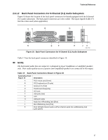
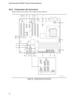
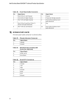
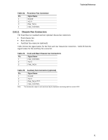
Technical Reference Table 23. Processor Fan Connector Pin Signal Name 1 Ground 2 +12 V 3 FAN_TACH 4 FAN_CONTROL 2.8.2.1 Chassis Fan Connectors The board has two standard and one optional chassis fan connectors: • Front chassis fan • Rear chassis fan • Auxiliary fan connector (optional) Table 24 lists the signal names for the front and rear chassis fan connectors. Table 26 lists the signal names for the auxiliary fan connector. Table 24. Front and Rear Chassis Fan Connectors Pin Signal Name 1 FAN_CONTROL 2 +12 V 3 FAN_TACH Table 25. Auxiliary Fan Connector (optional) Pin Signal Name 1 Ground 2 +12 V 3 FAN_TACH (Note) 4 FAN_CONTROL Note: The tachometer output is not monitored by the hardware monitoring and fan control ASIC. 61
-
 1
1 -
2
-
3
-
4
-
5
-
6
-
7
-
8
-
9
-
10
-
11
-
12
-
13
-
14
-
15
-
16
-
17
-
18
-
19
-
20
-
21
-
22
-
23
-
24
-
25
-
26
-
27
-
28
-
29
-
30
-
31
-
32
-
33
-
34
-
35
-
36
-
37
-
38
-
39
-
40
-
41
-
42
-
43
-
44
-
45
-
46
-
47
-
48
-
49
-
50
-
51
-
52
-
53
-
54
-
55
-
 56
56 -
 57
57 -
 58
58 -
 59
59 -
 60
60 -
 61
61 -
 62
62 -
 63
63 -
 64
64 -
 65
65 -
 66
66 -
67
-
68
-
69
-
70
-
71
-
72
-
73
-
74
-
75
-
76
-
77
-
78
-
79
-
80
-
81
-
82
-
83
-
84
-
85
-
86
-
87
-
88
-
89
-
90
-
91
-
92
-
93
-
94
 |
 |
Technical Reference
61
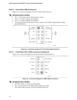
Table 23.
Processor Fan Connector
Pin
Signal Name
1
Ground
2
+12 V
3
FAN_TACH
4
FAN_CONTROL
2.8.2.1
Chassis Fan Connectors
The board has two standard and one optional chassis fan connectors:
•
Front chassis fan
•
Rear chassis fan
•
Auxiliary fan connector (optional)
Table 24 lists the signal names for the front and rear chassis fan connectors.
Table 26 lists the
signal names for the auxiliary fan connector.
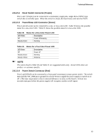
Table 24.
Front and Rear Chassis Fan Connectors
Pin
Signal Name
1
FAN_CONTROL
2
+12 V
3
FAN_TACH
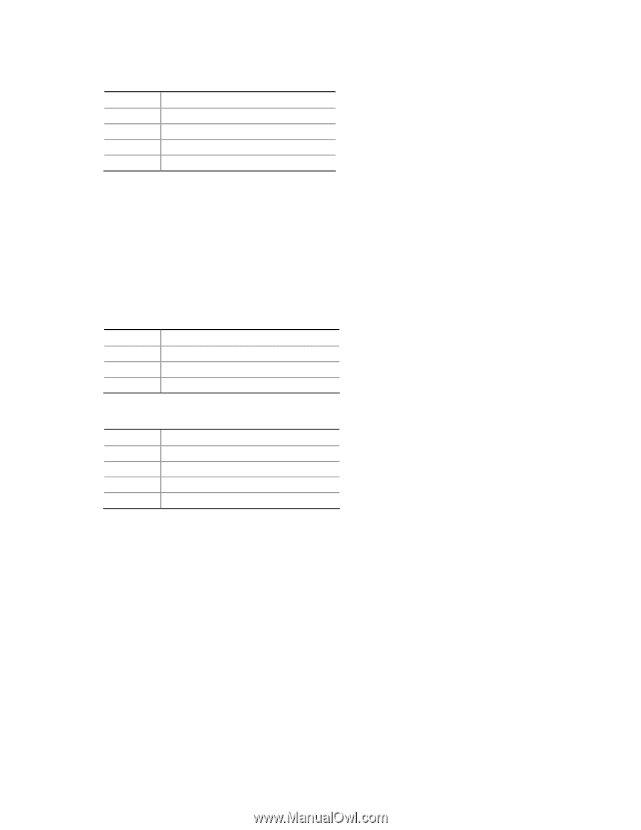
Table 25.
Auxiliary Fan Connector (optional)
Pin
Signal Name
1
Ground
2
+12 V
3
FAN_TACH
(Note)
4
FAN_CONTROL
Note:
The tachometer output is not monitored by the hardware monitoring and fan control ASIC.