Intel D945GNT Product Specification - Page 62
Power Supply Connectors, INTEGRATOR'S NOTE
 |
View all Intel D945GNT manuals
Add to My Manuals
Save this manual to your list of manuals |
Page 62 highlights
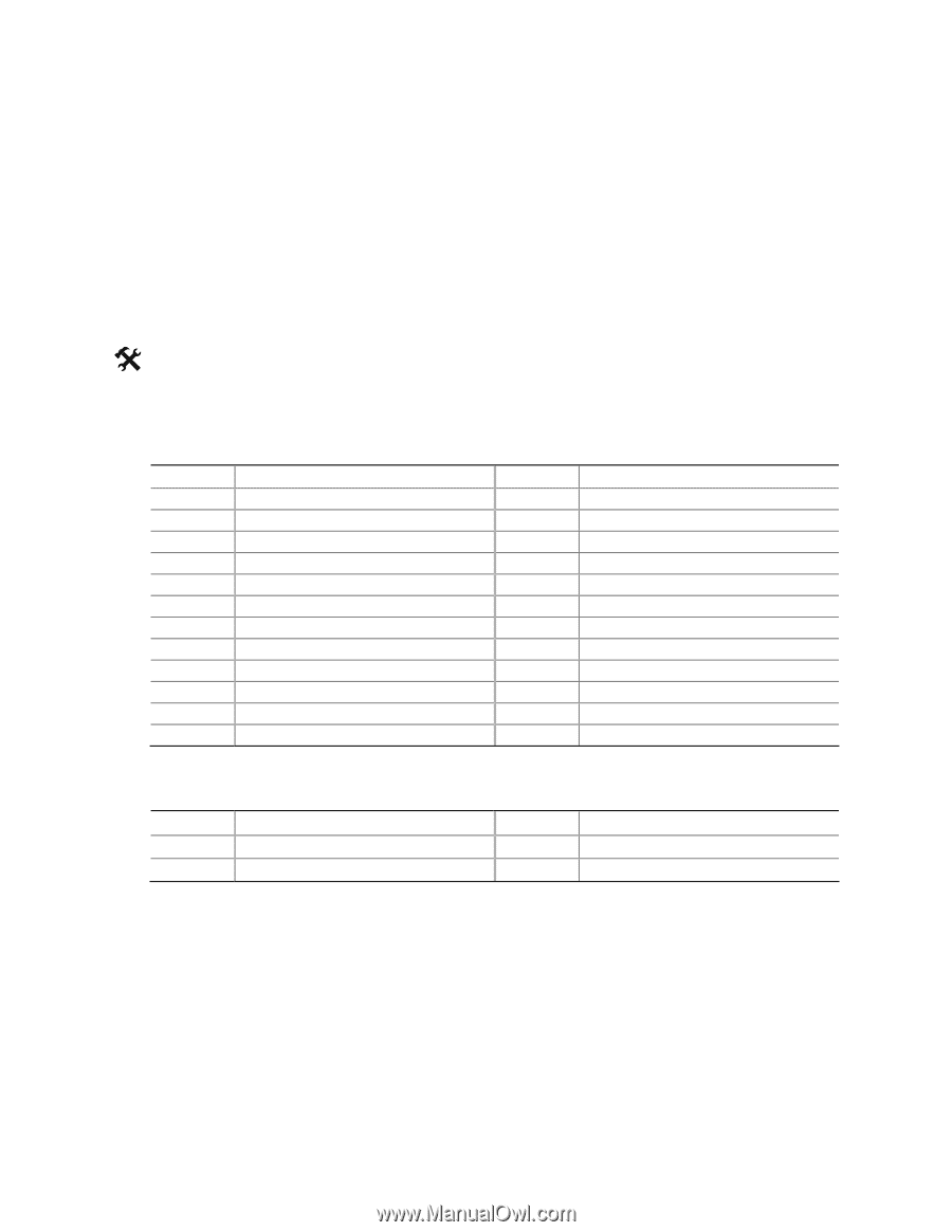
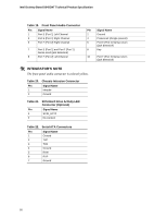
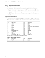
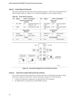
Intel Desktop Board D945GNT Technical Product Specification 2.8.2.2 Power Supply Connectors The board has power supply connectors: • Main power - a 2 x 12 connector. This connector is compatible with 2 x 10 connectors previously used on Intel desktop boards. The board supports the use of ATX12V power supplies with either 2 x 10 or 2 x 12 main power cables. When using a power supply with a 2 x 10 main power cable, attach that cable on the rightmost pins of the main power connector, leaving pins 11, 12, 23, and 24 unconnected. • ATX12V power - a 2 x 2 connector. This connector provides power directly to the processor voltage regulator and must always be used. Failure to do so will prevent the board from booting. # INTEGRATOR'S NOTE When using high wattage PCI Express x16 graphics cards, use a power supply with a 2 x 12 main power cable. The 2 x 12 main power cable can provide up to 144 W of power from the +12 V rail. Table 26. Main Power Connector Pin Signal Name Pin Signal Name 1 +3.3 V 13 +3.3 V 2 +3.3 V 14 -12 V 3 Ground 15 Ground 4 +5 V 16 PS-ON# (power supply remote on/off) 5 Ground 17 Ground 6 +5 V 18 Ground 7 Ground 19 Ground 8 PWRGD (Power Good) 20 No connect 9 +5 V (Standby) 21 +5 V 10 +12 V 11 +12 V (Note) 12 2 x 12 connector detect (Note) 22 +5 V 23 +5 V (Note) 24 Ground (Note) Note: When using a 2 x 10 power supply cable, this pin will be unconnected. Table 27. ATX12V Power Connector Pin Signal Name 1 Ground 3 +12 V Pin Signal Name 2 Ground 4 +12 V 62
-
 1
1 -
2
-
3
-
4
-
5
-
6
-
7
-
8
-
9
-
10
-
11
-
12
-
13
-
14
-
15
-
16
-
17
-
18
-
19
-
20
-
21
-
22
-
23
-
24
-
25
-
26
-
27
-
28
-
29
-
30
-
31
-
32
-
33
-
34
-
35
-
36
-
37
-
38
-
39
-
40
-
41
-
42
-
43
-
44
-
45
-
46
-
47
-
48
-
49
-
50
-
51
-
52
-
53
-
54
-
55
-
56
-
 57
57 -
 58
58 -
 59
59 -
 60
60 -
 61
61 -
 62
62 -
 63
63 -
 64
64 -
 65
65 -
 66
66 -
 67
67 -
68
-
69
-
70
-
71
-
72
-
73
-
74
-
75
-
76
-
77
-
78
-
79
-
80
-
81
-
82
-
83
-
84
-
85
-
86
-
87
-
88
-
89
-
90
-
91
-
92
-
93
-
94
 |
 |