Intel D945GNT Product Specification - Page 7

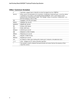
Error Messages and Beep Codes, s, Tables - processor support

Page 7 highlights

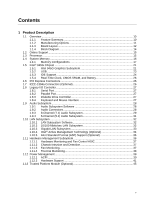
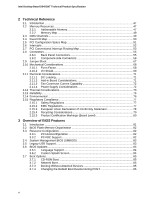
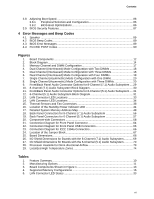
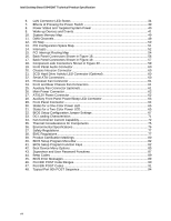
Contents 3.8 Adjusting Boot Speed 86 3.8.1 Peripheral Selection and Configuration 86 3.8.2 BIOS Boot Optimizations 86 3.9 BIOS Security Features 87 4 Error Messages and Beep Codes 4.1 Speaker ...89 4.2 BIOS Beep Codes...89 4.3 BIOS Error Messages 89 4.4 Port 80h POST Codes 90 Figures 1. Board Components ...12 2. Block Diagram...14 3. Memory Channel and DIMM Configuration 17 4. Dual Channel (Interleaved) Mode Configuration with Two DIMMs 18 5. Dual Channel (Interleaved) Mode Configuration with Three DIMMs 18 6. Dual Channel (Interleaved) Mode Configuration with Four DIMMs 19 7. Single Channel (Asymmetric) Mode Configuration with One DIMM 20 8. Single Channel (Asymmetric) Mode Configuration with Three DIMMs 20 9. Front/Back Panel Audio Connector Options for 8-Channel (7.1) Audio Subsystem .... 29 10. 8-channel (7.1) Audio Subsystem Block Diagram 30 11. Front/Back Panel Audio Connector Options for 6-Channel (5.1) Audio Subsystem .... 31 12. 6-Channel (5.1) Audio Subsystem Block Diagram 31 13. LAN Connector LED Locations 33 14. LAN Connector LED Locations 34 15. Thermal Sensors and Fan Connectors 38 16. Location of the Standby Power Indicator LED 44 17. Detailed System Memory Address Map 48 18. Back Panel Connectors for 8-Channel (7.1) Audio Subsystem 56 19. Back Panel Connectors for 6-Channel (5.1) Audio Subsystem 57 20. Component-side Connectors 58 21. Connection Diagram for Front Panel Connector 64 22. Connection Diagram for Front Panel USB Connectors 66 23. Connection Diagram for IEEE 1394a Connectors 66 24. Location of the Jumper Block 67 25. Board Dimensions...68 26. I/O Shield Dimensions for Boards with the 8-Channel (7.1) Audio Subsystem 69 27. I/O Shield Dimensions for Boards with the 6-Channel (5.1) Audio Subsystem 70 28. Processor Heatsink for Omni-directional Airflow 73 29. Localized High Temperature Zones 74 Tables 1. Feature Summary ...10 2. Manufacturing Options 11 3. Board Components Shown in Figure 1 13 4. Supported Memory Configurations 16 5. LAN Connector LED States 33 vii

  • 1
  • 2
  • 3
  • 4
  • 5
  • 6
  • 7
  • 8
  • 9
  • 10
  • 11
  • 12
  • 13
  • 14
  • 15
  • 16
  • 17
  • 18
  • 19
  • 20
  • 21
  • 22
  • 23
  • 24
  • 25
  • 26
  • 27
  • 28
  • 29
  • 30
  • 31
  • 32
  • 33
  • 34
  • 35
  • 36
  • 37
  • 38
  • 39
  • 40
  • 41
  • 42
  • 43
  • 44
  • 45
  • 46
  • 47
  • 48
  • 49
  • 50
  • 51
  • 52
  • 53
  • 54
  • 55
  • 56
  • 57
  • 58
  • 59
  • 60
  • 61
  • 62
  • 63
  • 64
  • 65
  • 66
  • 67
  • 68
  • 69
  • 70
  • 71
  • 72
  • 73
  • 74
  • 75
  • 76
  • 77
  • 78
  • 79
  • 80
  • 81
  • 82
  • 83
  • 84
  • 85
  • 86
  • 87
  • 88
  • 89
  • 90
  • 91
  • 92
  • 93
  • 94

Contents
vii
3.8
Adjusting Boot Speed
...................................................................................................
86
3.8.1
Peripheral Selection and Configuration
.........................................................
86
3.8.2
BIOS Boot Optimizations
...............................................................................
86
3.9
BIOS Security Features
...............................................................................................
87
4
Error Messages and Beep Codes
4.1
Speaker
.......................................................................................................................
89
4.2
BIOS Beep Codes
........................................................................................................
89
4.3
BIOS Error Messages
..................................................................................................
89
4.4
Port 80h POST Codes
.................................................................................................
90
Figures
1.
Board Components
......................................................................................................
12
2.
Block Diagram
..............................................................................................................
14
3.
Memory Channel and DIMM Configuration
..................................................................
17
4.
Dual Channel (Interleaved) Mode Configuration with Two DIMMs
..............................
18
5.
Dual Channel (Interleaved) Mode Configuration with Three DIMMs
............................
18
6.
Dual Channel (Interleaved) Mode Configuration with Four DIMMs
..............................
19
7.
Single Channel (Asymmetric) Mode Configuration with One DIMM
.............................
20
8.
Single Channel (Asymmetric) Mode Configuration with Three DIMMs
........................
20
9.
Front/Back Panel Audio Connector Options for 8-Channel (7.1) Audio Subsystem
....
29
10.
8-channel (7.1) Audio Subsystem Block Diagram
........................................................
30
11.
Front/Back Panel Audio Connector Options for 6-Channel (5.1) Audio Subsystem
....
31
12.
6-Channel (5.1) Audio Subsystem Block Diagram
.......................................................
31
13.
LAN Connector LED Locations
....................................................................................
33
14.
LAN Connector LED Locations
....................................................................................
34
15.
Thermal Sensors and Fan Connectors
........................................................................
38
16.
Location of the Standby Power Indicator LED
.............................................................
44
17.
Detailed System Memory Address Map
.......................................................................
48
18.
Back Panel Connectors for 8-Channel (7.1) Audio Subsystem
...................................
56
19.
Back Panel Connectors for 6-Channel (5.1) Audio Subsystem
...................................
57
20.
Component-side Connectors
.......................................................................................
58
21.
Connection Diagram for Front Panel Connector
..........................................................
64
22.
Connection Diagram for Front Panel USB Connectors
................................................
66
23.
Connection Diagram for IEEE 1394a Connectors
........................................................
66
24.
Location of the Jumper Block
.......................................................................................
67
25.
Board Dimensions
........................................................................................................
68
26.
I/O Shield Dimensions for Boards with the 8-Channel (7.1) Audio Subsystem
............
69
27.
I/O Shield Dimensions for Boards with the 6-Channel (5.1) Audio Subsystem
............
70
28.
Processor Heatsink for Omni-directional Airflow
..........................................................
73
29.
Localized High Temperature Zones
.............................................................................
74
Tables
1.
Feature Summary
........................................................................................................
10
2.
Manufacturing Options
.................................................................................................
11
3.
Board Components Shown in Figure 1
........................................................................
13
4.
Supported Memory Configurations
..............................................................................
16
5.
LAN Connector LED States
.........................................................................................
33