Intel DG33TL Product Guide - Page 49
Connecting to the HD Audio Link Header, Connecting to the IEEE 1394a Header
 |
View all Intel DG33TL manuals
Add to My Manuals
Save this manual to your list of manuals |
Page 49 highlights
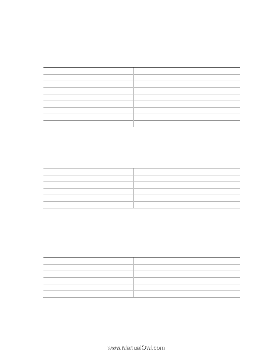
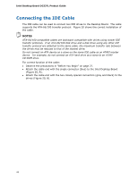
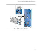
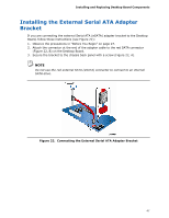
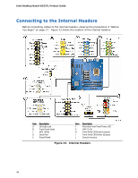
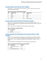
Installing and Replacing Desktop Board Components Connecting to the HD Audio Link Header See Figure 23, A for the location of the HD Audio Link header. Table 5 shows the pin assignments for the header. Table 5. HD Audio Link Header Signal Names Pin Signal Name 1 BCLK 3 RST# Pin Signal Name 2 Ground 4 3.3 Vcc 5 SYNC 6 Ground 7 SDO 9 SDI0 11 SDI1 8 3.3 Vcc 10 +12 V 12 Key 13 No Connection 14 3.3 V STBY 15 No Connection 16 Ground Connecting to the IEEE 1394a Header See Figure 23, C for the location of the IEEE 1394a header. Table 6 shows the pin assignments for the header. Table 6. IEEE 1394a Signal Header Names Pin Signal Name 1 TPA1+ Pin Signal Name 2 TPA1- 3 Ground 4 Ground 5 TPA2+ 6 TPA2- 7 +12 V 9 Key (no pin) 8 +12 V 10 Ground Installing a Front Panel Audio Solution for Intel® High Definition Audio Figure 23, B shows the location of the front panel audio header. Table 7 shows the pin assignments for the front panel audio header. Table 7. Front Panel Intel High Definition Audio Header Signal Names Pin Signal Name 1 PORT 1L 3 PORT 1R 5 PORT 2R 7 SENSE_SEND 9 PORT 2L Pin Signal Name 2 GND 4 PRESENCE# 6 SENSE1_RETURN 8 KEY (no pin) 10 SENSE2_RETURN 49
-
 1
1 -
2
-
3
-
4
-
5
-
6
-
7
-
8
-
9
-
10
-
11
-
12
-
13
-
14
-
15
-
16
-
17
-
18
-
19
-
20
-
21
-
22
-
23
-
24
-
25
-
26
-
27
-
28
-
29
-
30
-
31
-
32
-
33
-
34
-
35
-
36
-
37
-
38
-
39
-
40
-
41
-
42
-
43
-
 44
44 -
 45
45 -
 46
46 -
 47
47 -
 48
48 -
 49
49 -
 50
50 -
 51
51 -
 52
52 -
 53
53 -
 54
54 -
55
-
56
-
57
-
58
-
59
-
60
-
61
-
62
-
63
-
64
-
65
-
66
-
67
-
68
-
69
-
70
-
71
-
72
-
73
-
74
-
75
-
76
-
77
-
78
-
79
-
80
-
81
-
82
-
83
-
84
-
85
-
86
-
87
-
88
-
89
-
90
 |
 |