Intel DG33TL Product Guide - Page 8

Tables, Back Panel CIR Header Emitter Output Header Signal Names - board

Page 8 highlights

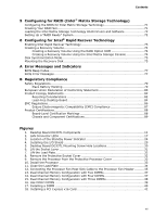
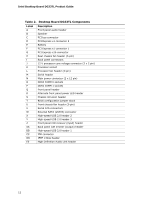
Intel Desktop Board DG33TL Product Guide 19. Removing a PCI Express x16 Card 43 20. Connecting the IDE Cable 45 21. Connecting a Serial ATA Cable 46 22. Connecting the External Serial ATA Adapter Bracket 47 23. Internal Headers 48 24. Back Panel Audio Connectors 53 25. Location of the Chassis Fan Headers 54 26. Connecting Power Supply Cables 55 27. Location of the BIOS Configuration Jumper Block 56 28. Removing the Battery 63 Tables 1. Feature Summary 9 2. Desktop Board DG33TL Components 12 3. DVI/VGA Port Status 16 4. LAN Connector LEDs 18 5. HD Audio Link Header Signal Names 49 6. IEEE 1394a Signal Header Names 49 7. Front Panel Intel High Definition Audio Header Signal Names 49 8. Front Panel CIR Receiver (Input) Header Signal Names 50 9. Back Panel CIR Header Emitter (Output) Header Signal Names 50 10. Serial Port Header Signal Names 51 11. Chassis Intrusion Header 51 12. Alternate Front Panel Power LED Header 51 13. Front Panel Header 52 14. USB 2.0 Header Signal Names 52 15. Jumper Settings for the BIOS Setup Program Modes 57 16. Beep Codes 77 17. BIOS Error Messages 77 18. Safety Regulations 79 19. Lead-Free Board Markings 85 20. EMC Regulations 86 21. Product Certification Markings 88 viii

  • 1
  • 2
  • 3
  • 4
  • 5
  • 6
  • 7
  • 8
  • 9
  • 10
  • 11
  • 12
  • 13
  • 14
  • 15
  • 16
  • 17
  • 18
  • 19
  • 20
  • 21
  • 22
  • 23
  • 24
  • 25
  • 26
  • 27
  • 28
  • 29
  • 30
  • 31
  • 32
  • 33
  • 34
  • 35
  • 36
  • 37
  • 38
  • 39
  • 40
  • 41
  • 42
  • 43
  • 44
  • 45
  • 46
  • 47
  • 48
  • 49
  • 50
  • 51
  • 52
  • 53
  • 54
  • 55
  • 56
  • 57
  • 58
  • 59
  • 60
  • 61
  • 62
  • 63
  • 64
  • 65
  • 66
  • 67
  • 68
  • 69
  • 70
  • 71
  • 72
  • 73
  • 74
  • 75
  • 76
  • 77
  • 78
  • 79
  • 80
  • 81
  • 82
  • 83
  • 84
  • 85
  • 86
  • 87
  • 88
  • 89
  • 90

Intel Desktop Board DG33TL Product Guide
viii
19. Removing a PCI Express x16 Card
..................................................................
43
20. Connecting the IDE Cable
..............................................................................
45
21. Connecting a Serial ATA Cable
........................................................................
46
22. Connecting the External Serial ATA Adapter Bracket
..........................................
47
23. Internal Headers
..........................................................................................
48
24. Back Panel Audio Connectors
.........................................................................
53
25. Location of the Chassis Fan Headers
................................................................
54
26. Connecting Power Supply Cables
....................................................................
55
27. Location of the BIOS Configuration Jumper Block
..............................................
56
28. Removing the Battery
...................................................................................
63
Tables
1.
Feature Summary
..........................................................................................
9
2.
Desktop Board DG33TL Components
...............................................................
12
3.
DVI/VGA Port Status
.....................................................................................
16
4.
LAN Connector LEDs
.....................................................................................
18
5.
HD Audio Link Header Signal Names
...............................................................
49
6.
IEEE 1394a Signal Header Names
...................................................................
49
7.
Front Panel Intel High Definition Audio Header Signal Names
..............................
49
8.
Front Panel CIR Receiver (Input) Header Signal Names
......................................
50
9.
Back Panel CIR Header Emitter (Output) Header Signal Names
...........................
50
10.
Serial Port Header Signal Names
.....................................................................
51
11.
Chassis Intrusion Header
...............................................................................
51
12.
Alternate Front Panel Power LED Header
..........................................................
51
13.
Front Panel Header
.......................................................................................
52
14.
USB 2.0 Header Signal Names
........................................................................
52
15.
Jumper Settings for the BIOS Setup Program Modes
..........................................
57
16.
Beep Codes
.................................................................................................
77
17.
BIOS Error Messages
....................................................................................
77
18.
Safety Regulations
........................................................................................
79
19.
Lead-Free Board Markings
.............................................................................
85
20.
EMC Regulations
...........................................................................................
86
21.
Product Certification Markings
........................................................................
88