Intel DG33TL Product Guide - Page 7

Connecting the Processor Fan Heat Sink Cable to the Processor Fan Header - bios

Page 7 highlights

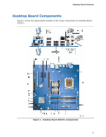
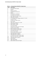
Contents 5 Configuring for RAID (Intel® Matrix Storage Technology) Configuring the BIOS for Intel Matrix Storage Technology 71 Creating Your RAID Set 71 Loading the Intel Matrix Storage Technology RAID Drivers and Software 72 Setting Up a "RAID Ready" System 72 6 Configuring for Intel® Rapid Recover Technology Enabling Intel Rapid Recover Technology 73 Creating a Recovery Volume 74 Creating a Recovery Volume Using the RAID Option ROM 74 Creating a Recovery Volume Using the Intel Matrix Storage Console 74 Disk Synchronization Mode 75 Mounting the Recovery Disk 75 A Error Messages and Indicators BIOS Beep Codes 77 BIOS Error Messages 77 B Regulatory Compliance Safety Regulations 79 Place Battery Marking 79 European Union Declaration of Conformity Statement 80 Product Ecology Statements 82 Recycling Considerations 82 Lead-Free Desktop Board 84 EMC Regulations 86 Ensure Electromagnetic Compatibility (EMC) Compliance 87 Product Certifications 88 Board-Level Certification Markings 88 Chassis and Component Certifications 89 Figures 1. Desktop Board DG33TL Components 11 2. LAN Connector LEDs 17 3. Location of the Standby Power Indicator 24 4. Installing the I/O Shield 29 5. Desktop Board DG33TL Mounting Screw Hole Locations 30 6. Lift the Socket Lever 31 7. Lift the Load Plate 32 8. Remove the Protective Socket Cover 32 9. Remove the Processor from the Protective Processor Cover 33 10. Install the Processor 33 11. Close the Load Plate 34 12. Connecting the Processor Fan Heat Sink Cable to the Processor Fan Header ..........35 13. Dual Channel Memory Configuration with Two DIMMs 37 14. Dual Channel Memory Configuration with Four DIMMs 37 15. Dual Channel Memory Configuration with Three DIMMs 38 16. Use DDR2 DIMMs 39 17. Installing a DIMM 40 18. Installing a PCI Express x16 Card 42 vii

  • 1
  • 2
  • 3
  • 4
  • 5
  • 6
  • 7
  • 8
  • 9
  • 10
  • 11
  • 12
  • 13
  • 14
  • 15
  • 16
  • 17
  • 18
  • 19
  • 20
  • 21
  • 22
  • 23
  • 24
  • 25
  • 26
  • 27
  • 28
  • 29
  • 30
  • 31
  • 32
  • 33
  • 34
  • 35
  • 36
  • 37
  • 38
  • 39
  • 40
  • 41
  • 42
  • 43
  • 44
  • 45
  • 46
  • 47
  • 48
  • 49
  • 50
  • 51
  • 52
  • 53
  • 54
  • 55
  • 56
  • 57
  • 58
  • 59
  • 60
  • 61
  • 62
  • 63
  • 64
  • 65
  • 66
  • 67
  • 68
  • 69
  • 70
  • 71
  • 72
  • 73
  • 74
  • 75
  • 76
  • 77
  • 78
  • 79
  • 80
  • 81
  • 82
  • 83
  • 84
  • 85
  • 86
  • 87
  • 88
  • 89
  • 90

Contents
vii
5
Configuring for RAID (Intel
®
Matrix Storage Technology)
Configuring the BIOS for Intel Matrix Storage Technology
........................................
71
Creating Your RAID Set
.......................................................................................
71
Loading the Intel Matrix Storage Technology RAID Drivers and Software
....................
72
Setting Up a “RAID Ready” System
.......................................................................
72
6
Configuring for Intel
®
Rapid Recover Technology
Enabling Intel Rapid Recover Technology
...............................................................
73
Creating a Recovery Volume
................................................................................
74
Creating a Recovery Volume Using the RAID Option ROM
.................................
74
Creating a Recovery Volume Using the Intel Matrix Storage Console
..................
74
Disk Synchronization Mode
..................................................................................
75
Mounting the Recovery Disk
................................................................................
75
A
Error Messages and Indicators
BIOS Beep Codes
...............................................................................................
77
BIOS Error Messages
..........................................................................................
77
B
Regulatory Compliance
Safety Regulations
.............................................................................................
79
Place Battery Marking
.................................................................................
79
European Union Declaration of Conformity Statement
..............................................
80
Product Ecology Statements
................................................................................
82
Recycling Considerations
.............................................................................
82
Lead-Free Desktop Board
.............................................................................
84
EMC Regulations
................................................................................................
86
Ensure Electromagnetic Compatibility (EMC) Compliance
..................................
87
Product Certifications
..........................................................................................
88
Board-Level Certification Markings
................................................................
88
Chassis and Component Certifications
............................................................
89
Figures
1. Desktop Board DG33TL Components
...............................................................
11
2. LAN Connector LEDs
.....................................................................................
17
3.
Location of the Standby Power Indicator
..........................................................
24
4. Installing the I/O Shield
................................................................................
29
5.
Desktop Board DG33TL Mounting Screw Hole Locations
......................................
30
6. Lift the Socket Lever
.....................................................................................
31
7. Lift the Load Plate
.........................................................................................
32
8. Remove the Protective Socket Cover
...............................................................
32
9.
Remove the Processor from the Protective Processor Cover
................................
33
10. Install the Processor
.....................................................................................
33
11. Close the Load Plate
.....................................................................................
34
12. Connecting the Processor Fan Heat Sink Cable to the Processor Fan Header
..........
35
13. Dual Channel Memory Configuration with Two DIMMs
........................................
37
14. Dual Channel Memory Configuration with Four DIMMs
........................................
37
15. Dual Channel Memory Configuration with Three DIMMs
......................................
38
16. Use DDR2 DIMMs
.........................................................................................
39
17. Installing a DIMM
.........................................................................................
40
18. Installing a PCI Express x16 Card
...................................................................
42