Intel DG965OT Product Guide - Page 46
Connecting to the HD Audio Link Header, Connecting to the Flexible Audio System - sigmatel
 |
UPC - 735858186049
View all Intel DG965OT manuals
Add to My Manuals
Save this manual to your list of manuals |
Page 46 highlights
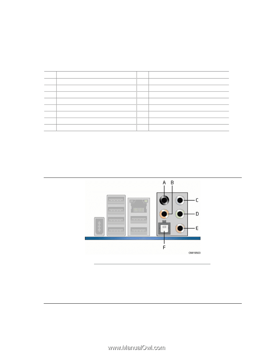
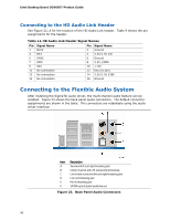
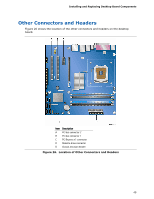
Intel Desktop Board DG965OT Product Guide Connecting to the HD Audio Link Header See Figure 22, A for the location of the HD Audio Link header. Table 9 shows the pin assignments for the header. Table 11. HD Audio Link Header Signal Names Pin Signal Name Pin Signal Name 1 BLCK 3 RST 5 SYNC 2 Ground 4 3.3V/1.5V I/O 6 Ground 7 SDO 8 3.3V_CORE 9 SDI 11 No connection 13 No connection 10 +12V 12 Key (no pin) 14 3.3V/1.5V STBY 15 No connection 16 Ground Connecting to the Flexible Audio System After installing the SigmaTel audio driver, the multi-channel audio feature can be enabled. Figure 23 shows the back panel audio connectors. The default connector assignments are shown in the table. The connectors are retaskable using the audio driver interface. Item Description A Surround left and right/retasking jack B Center channel and LFE (subwoofer)/retasking C Line in/side surround left and right/retasking jack D Line out/retasking jack E Mic in/retasking jack F S/PDIF optical digital audio line out Figure 23. Back Panel Audio Connectors 46
-
 1
1 -
2
-
3
-
4
-
5
-
6
-
7
-
8
-
9
-
10
-
11
-
12
-
13
-
14
-
15
-
16
-
17
-
18
-
19
-
20
-
21
-
22
-
23
-
24
-
25
-
26
-
27
-
28
-
29
-
30
-
31
-
32
-
33
-
34
-
35
-
36
-
37
-
38
-
39
-
40
-
 41
41 -
 42
42 -
 43
43 -
 44
44 -
 45
45 -
 46
46 -
 47
47 -
 48
48 -
 49
49 -
 50
50 -
 51
51 -
52
-
53
-
54
-
55
-
56
-
57
-
58
-
59
-
60
-
61
-
62
-
63
-
64
-
65
-
66
-
67
-
68
-
69
-
70
-
71
-
72
-
73
-
74
-
75
-
76
-
77
-
78
-
79
-
80
-
81
-
82
 |
 |