Intel DG965OT Product Guide - Page 51
Clearing Passwords, Table 12. Jumper Settings for the BIOS Setup Program Modes
 |
UPC - 735858186049
View all Intel DG965OT manuals
Add to My Manuals
Save this manual to your list of manuals |
Page 51 highlights
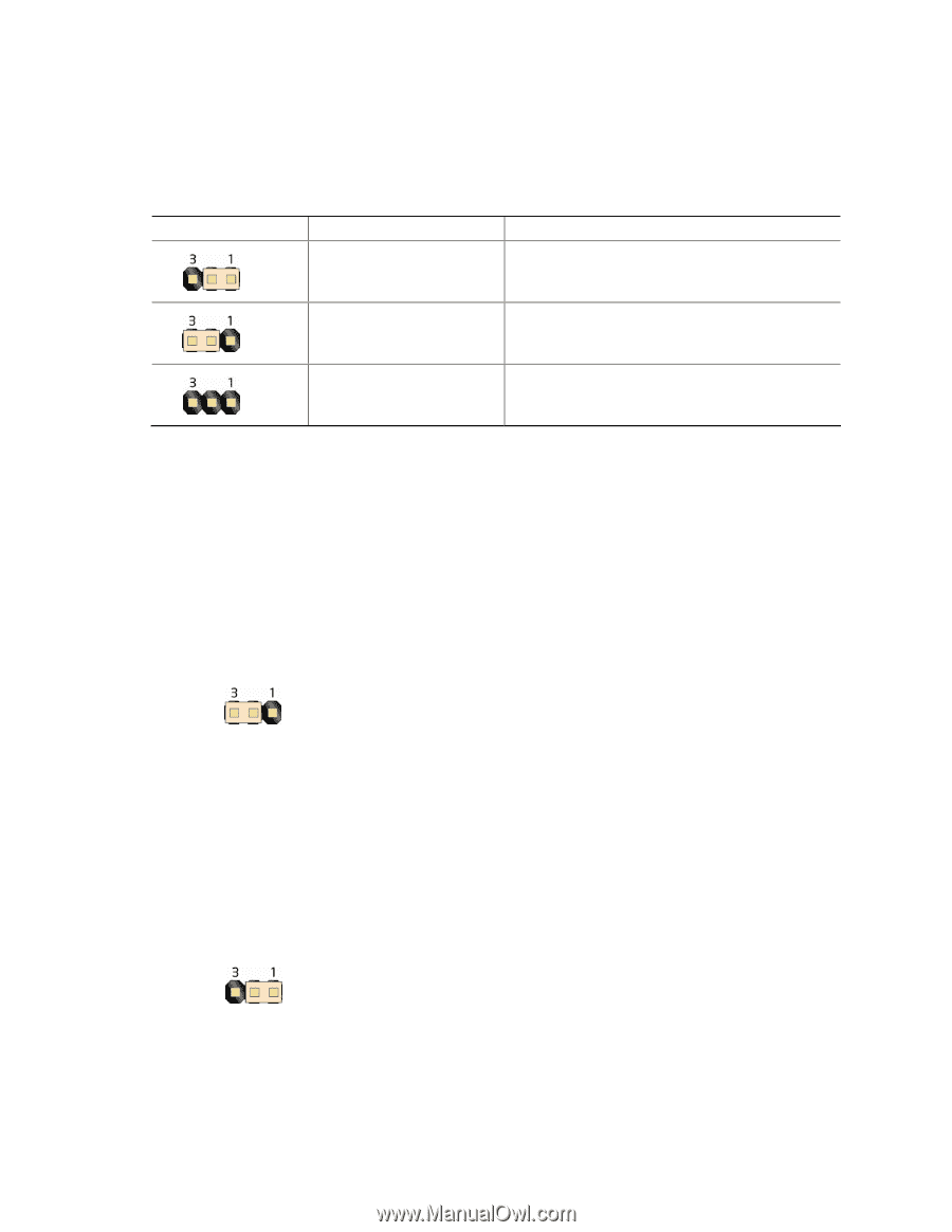
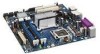
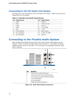
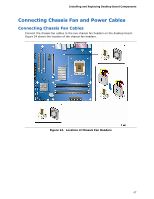
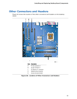
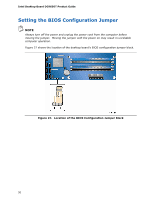
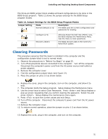
Installing and Replacing Desktop Board Components The three-pin BIOS jumper block enables all board configurations to be done in the BIOS Setup program. Table 12 shows the jumper settings for the BIOS Setup program modes. Table 12. Jumper Settings for the BIOS Setup Program Modes Jumper Setting Mode Normal (default) (1-2) Description The BIOS uses the current configuration and passwords for booting. Configure (2-3) Recovery (None) After the Power-On Self-Test (POST) runs, the BIOS displays the Maintenance Menu. Use this menu to clear passwords. The BIOS recovers data in the event of a failed BIOS update. Clearing Passwords This procedure assumes that the board is installed in the computer and the configuration jumper block is set to normal mode. 1. Observe the precautions in "Before You Begin" on page 25. 2. Turn off all peripheral devices connected to the computer. Turn off the computer. Disconnect the computer's power cord from the AC power source (wall outlet or power adapter). 3. Remove the computer cover. 4. Find the configuration jumper block (see Figure 27). 5. Place the jumper on pins 2-3 as shown below. 6. Replace the cover, plug in the computer, turn on the computer, and allow it to boot. 7. The computer starts the Setup program. Setup displays the Maintenance menu. 8. Use the arrow keys to select Clear Passwords. Press and Setup displays a pop-up screen requesting that you confirm clearing the password. Select Yes and press . Setup displays the maintenance menu again. 9. Press to save the current values and exit Setup. 10. Turn off the computer. Disconnect the computer's power cord from the AC power source. 11. Remove the computer cover. 12. To restore normal operation, place the jumper on pins 1-2 as shown below. 13. Replace the cover, plug in the computer, and turn on the computer. 51
-
 1
1 -
2
-
3
-
4
-
5
-
6
-
7
-
8
-
9
-
10
-
11
-
12
-
13
-
14
-
15
-
16
-
17
-
18
-
19
-
20
-
21
-
22
-
23
-
24
-
25
-
26
-
27
-
28
-
29
-
30
-
31
-
32
-
33
-
34
-
35
-
36
-
37
-
38
-
39
-
40
-
41
-
42
-
43
-
44
-
45
-
 46
46 -
 47
47 -
 48
48 -
 49
49 -
 50
50 -
 51
51 -
 52
52 -
 53
53 -
 54
54 -
 55
55 -
 56
56 -
57
-
58
-
59
-
60
-
61
-
62
-
63
-
64
-
65
-
66
-
67
-
68
-
69
-
70
-
71
-
72
-
73
-
74
-
75
-
76
-
77
-
78
-
79
-
80
-
81
-
82
 |
 |