Intel DG965OT Product Guide - Page 7

Connecting the Processor Fan Heat Sink Cable to the Processor Fan Header - memory

Page 7 highlights

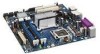
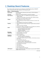
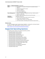
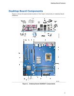
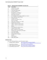
Contents 5 Intel® Quick Resume Technology Driver (Intel® QRTD) Overview...67 Intel Quick Resume Technology Power Modes 67 Installation and Configuration 68 A Error Messages and Indicators BIOS Beep Codes 71 BIOS Error Messages 71 B Regulatory Compliance Safety Regulations 73 Place Battery Marking 73 European Union Declaration of Conformity Statement 74 Product Ecology Statements 75 Lead-Free Desktop Board 78 EMC Regulations 79 Ensure Electromagnetic Compatibility (EMC) Compliance 80 Product Certifications 81 Board-Level Certification Markings 81 Chassis and Component Certifications 82 Figures 1. Desktop Board DG965OT Components 11 2. LAN Connector LEDs 17 3. Location of Standby Power Indicator 23 4. Installing the I/O Shield 27 5. Desktop Board DG965OT Mounting Screw Hole Locations 28 6. Lift Socket Lever 29 7. Lift the Load Plate 29 8. Remove the Protective Socket Cover 30 9. Remove the Processor from the Protective Processor Cover 30 10. Install the Processor 31 11. Close the Load Plate 31 12. Connecting the Processor Fan Heat Sink Cable to the Processor Fan Header.......... 32 13. Dual Channel Memory Configuration Example 1 33 14. Dual Channel Memory Configuration Example 2 34 15. Dual Channel Memory Configuration Example 3 34 16. Use DDR2 DIMMs 35 17. Installing a DIMM 36 18. Installing a PCI Express x16 Card 38 19. Removing a PCI Express x16 Card 39 20. Connecting the IDE Cable 40 21. Connecting the Serial ATA Cable 41 22. Internal Headers 42 23. Back Panel Audio Connectors 46 24. Location of Chassis Fan Headers 47 25. Connecting Power Supply Cables 48 26. Location of Other Connectors and Headers 49 27. Location of the BIOS Configuration Jumper Block 50 28. Back Panel Connectors 52 29. Removing the Battery 57 vii

  • 1
  • 2
  • 3
  • 4
  • 5
  • 6
  • 7
  • 8
  • 9
  • 10
  • 11
  • 12
  • 13
  • 14
  • 15
  • 16
  • 17
  • 18
  • 19
  • 20
  • 21
  • 22
  • 23
  • 24
  • 25
  • 26
  • 27
  • 28
  • 29
  • 30
  • 31
  • 32
  • 33
  • 34
  • 35
  • 36
  • 37
  • 38
  • 39
  • 40
  • 41
  • 42
  • 43
  • 44
  • 45
  • 46
  • 47
  • 48
  • 49
  • 50
  • 51
  • 52
  • 53
  • 54
  • 55
  • 56
  • 57
  • 58
  • 59
  • 60
  • 61
  • 62
  • 63
  • 64
  • 65
  • 66
  • 67
  • 68
  • 69
  • 70
  • 71
  • 72
  • 73
  • 74
  • 75
  • 76
  • 77
  • 78
  • 79
  • 80
  • 81
  • 82

Contents
vii
5
Intel
®
Quick Resume Technology Driver (Intel
®
QRTD)
Overview
............................................................................................................
67
Intel Quick Resume Technology Power Modes
.................................................
67
Installation and Configuration
...............................................................................
68
A
Error Messages and Indicators
BIOS Beep Codes
................................................................................................
71
BIOS Error Messages
...........................................................................................
71
B
Regulatory Compliance
Safety Regulations
..............................................................................................
73
Place Battery Marking
..................................................................................
73
European Union Declaration of Conformity Statement
..............................................
74
Product Ecology Statements
.................................................................................
75
Lead-Free Desktop Board
.............................................................................
78
EMC Regulations
.................................................................................................
79
Ensure Electromagnetic Compatibility (EMC) Compliance
..................................
80
Product Certifications
...........................................................................................
81
Board-Level Certification Markings
.................................................................
81
Chassis and Component Certifications
............................................................
82
Figures
1. Desktop Board DG965OT Components
.............................................................
11
2. LAN Connector LEDs
......................................................................................
17
3. Location of Standby Power Indicator
................................................................
23
4. Installing the I/O Shield
.................................................................................
27
5.
Desktop Board DG965OT Mounting Screw Hole Locations
...................................
28
6. Lift Socket Lever
...........................................................................................
29
7. Lift the Load Plate
..........................................................................................
29
8. Remove the Protective Socket Cover
................................................................
30
9.
Remove the Processor from the Protective Processor Cover
................................
30
10. Install the Processor
......................................................................................
31
11. Close the Load Plate
.......................................................................................
31
12. Connecting the Processor Fan Heat Sink Cable to the Processor Fan Header
..........
32
13. Dual Channel Memory Configuration Example 1
.................................................
33
14. Dual Channel Memory Configuration Example 2
.................................................
34
15. Dual Channel Memory Configuration Example 3
.................................................
34
16. Use DDR2 DIMMs
..........................................................................................
35
17. Installing a DIMM
..........................................................................................
36
18. Installing a PCI Express x16 Card
....................................................................
38
19. Removing a PCI Express x16 Card
...................................................................
39
20. Connecting the IDE Cable
...............................................................................
40
21. Connecting the Serial ATA Cable
......................................................................
41
22. Internal Headers
...........................................................................................
42
23. Back Panel Audio Connectors
..........................................................................
46
24. Location of Chassis Fan Headers
......................................................................
47
25. Connecting Power Supply Cables
.....................................................................
48
26. Location of Other Connectors and Headers
........................................................
49
27. Location of the BIOS Configuration Jumper Block
...............................................
50
28. Back Panel Connectors
...................................................................................
52
29. Removing the Battery
....................................................................................
57