Intel DH57JG Product Specification - Page 43
Signal Tables for the Connectors and Headers
 |
View all Intel DH57JG manuals
Add to My Manuals
Save this manual to your list of manuals |
Page 43 highlights
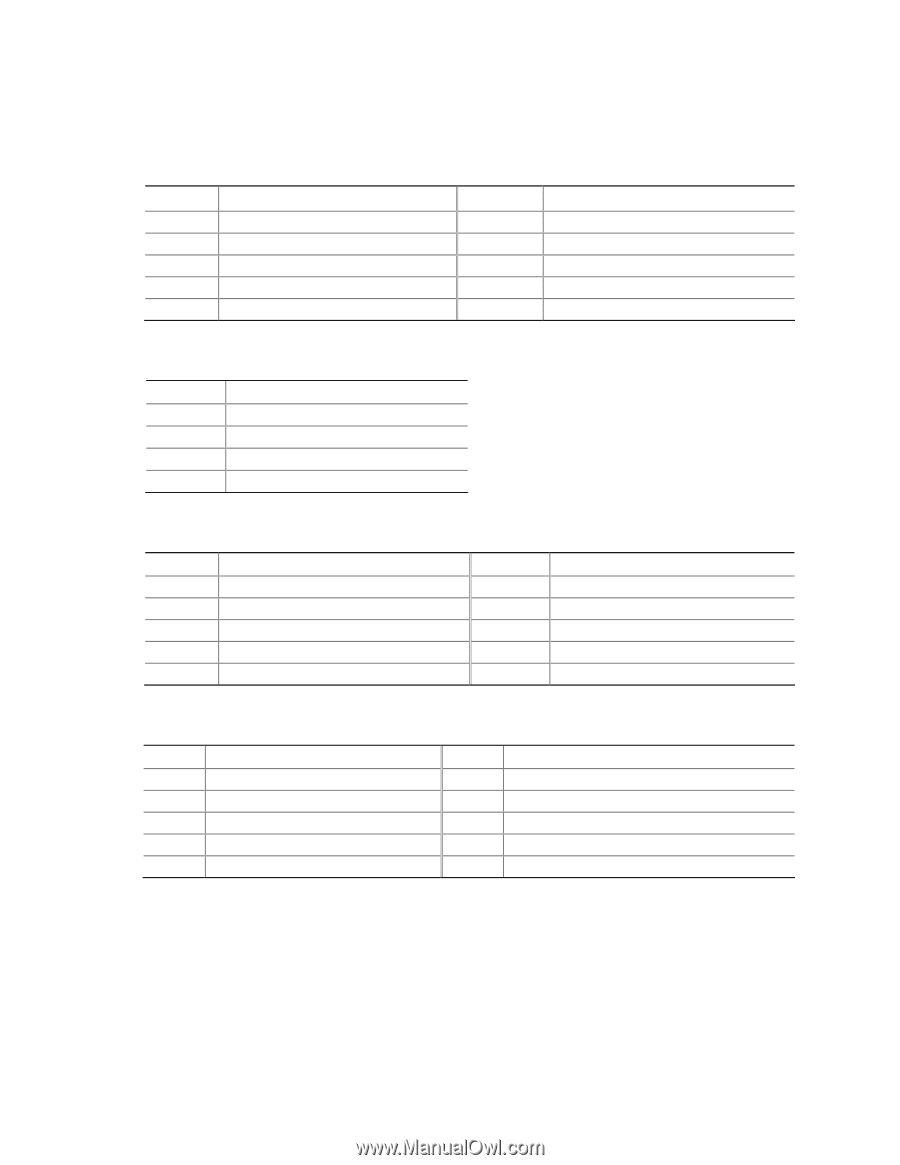
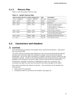
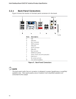
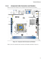
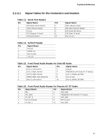
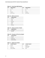
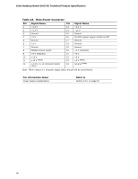
Technical Reference 2.2.2.1 Signal Tables for the Connectors and Headers Table 13. Serial Port Header Pin Signal Name 1 DCD (Data Carrier Detect) 3 TXD# (Transmit Data) 5 Ground 7 RTS (Request To Send) 9 RI (Ring Indicator) Pin 2 4 6 8 10 Signal Name RXD# (Receive Data) DTR (Data Terminal Ready) DSR (Data Set Ready) CTS (Clear To Send) Key (no pin) Table 14. S/PDIF Header Pin Signal Name 1 Ground 2 S/PDIF out 3 Key (no pin) 3 +5V_DC Table 15. Front Panel Audio Header for Intel HD Audio Pin Signal Name Pin Signal Name 1 [Port 1] Left channel 2 Ground 3 [Port 1] Right channel 4 PRESENCE# (HD Audio/AC '97 detect) 5 [Port 2] Right channel 6 [Port 1] SENSE_RETURN 7 SENSE_SEND (Jack detection) 8 Key (no pin) 9 [Port 2] Left channel 10 [Port 2] SENSE_RETURN Table 16. Front Panel Audio Header for Passive AC '97 Audio Pin Signal Name Pin Signal Name 1 MIC 3 MIC_BIAS 2 AUD_GND 4 PRESENCE# (HD Audio/AC '97 detect) 5 FP_OUT_R 6 AUD_GND 7 NC (no connect) 8 KEY (no pin) 9 FP_OUT_L 10 AUD_GND 43
-
 1
1 -
2
-
3
-
4
-
5
-
6
-
7
-
8
-
9
-
10
-
11
-
12
-
13
-
14
-
15
-
16
-
17
-
18
-
19
-
20
-
21
-
22
-
23
-
24
-
25
-
26
-
27
-
28
-
29
-
30
-
31
-
32
-
33
-
34
-
35
-
36
-
37
-
 38
38 -
 39
39 -
 40
40 -
 41
41 -
 42
42 -
 43
43 -
 44
44 -
 45
45 -
 46
46 -
 47
47 -
 48
48 -
49
-
50
-
51
-
52
-
53
-
54
-
55
-
56
-
57
-
58
-
59
-
60
-
61
-
62
-
63
-
64
-
65
-
66
-
67
-
68
-
69
-
70
-
71
-
72
-
73
-
74
-
75
-
76
-
77
-
78
-
79
-
80
-
81
-
82
-
83
-
84
-
85
-
86
 |
 |