Intel DH57JG Product Specification - Page 45
Add-in Card Connectors, 2.2.3, Power Supply Connectors, CAUTION
 |
View all Intel DH57JG manuals
Add to My Manuals
Save this manual to your list of manuals |
Page 45 highlights
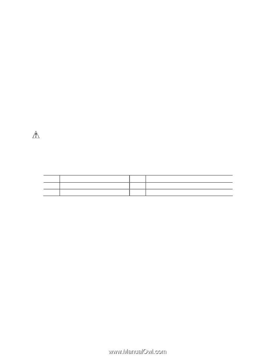
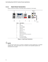
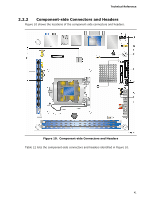
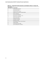
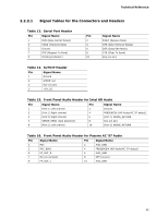
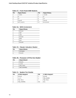
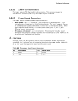
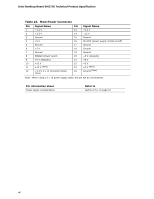
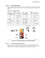
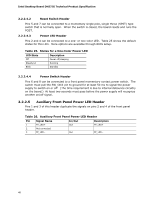
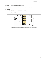
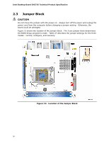
Technical Reference 2.2.2.2 Add-in Card Connectors The board has one PCI Express 2.0 x16 connector. This connector supports simultaneous transfer speeds of up to 8 GB/s of peak bandwidth. 2.2.2.3 Power Supply Connectors The board has the following power supply connectors: • Main power - a 2 x 12 connector. This connector is compatible with 2 x 10 connectors previously used on Intel Desktop boards. The board supports the use of ATX12V power supplies with either 2 x 10 or 2 x 12 main power cables. When using a power supply with a 2 x 10 main power cable, pins 11, 12, 23, and 24 must remain unconnected. • Processor core power - a 2 x 2 connector. This connector provides power directly to the processor voltage regulator and must always be used. Failure to do so will prevent the board from booting. CAUTION If a high power (75 W or greater) add-in card is installed in the PCI Express x16 connector, that card must also be connected directly to the power supply. Failure to do so may cause damage to the board and the add-in card. Table 22. Processor Core Power Connector Pin Signal Name Pin Signal Name 1 Ground 2 Ground 3 +12 V 4 +12 V 45
-
 1
1 -
2
-
3
-
4
-
5
-
6
-
7
-
8
-
9
-
10
-
11
-
12
-
13
-
14
-
15
-
16
-
17
-
18
-
19
-
20
-
21
-
22
-
23
-
24
-
25
-
26
-
27
-
28
-
29
-
30
-
31
-
32
-
33
-
34
-
35
-
36
-
37
-
38
-
39
-
 40
40 -
 41
41 -
 42
42 -
 43
43 -
 44
44 -
 45
45 -
 46
46 -
 47
47 -
 48
48 -
 49
49 -
 50
50 -
51
-
52
-
53
-
54
-
55
-
56
-
57
-
58
-
59
-
60
-
61
-
62
-
63
-
64
-
65
-
66
-
67
-
68
-
69
-
70
-
71
-
72
-
73
-
74
-
75
-
76
-
77
-
78
-
79
-
80
-
81
-
82
-
83
-
84
-
85
-
86
 |
 |