Intel DQ57TM Intel Desktop Board DQ57TM Product Guide English - Page 59
Intel RPAT Header, Serial Header
 |
View all Intel DQ57TM manuals
Add to My Manuals
Save this manual to your list of manuals |
Page 59 highlights
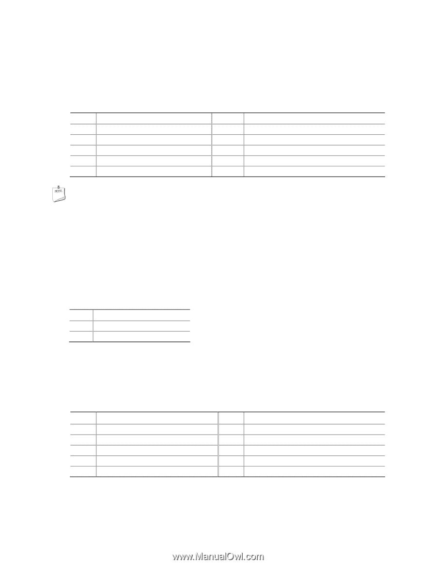
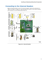
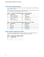
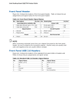
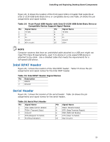
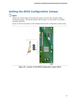
Installing and Replacing Desktop Board Components Figure 26, D shows the location of the front panel USB 2.0 header that supports an Intel Z-U130 USB Solid-State Drive or compatible device and Table 14 shows the pin assignments and signal names. Table 14. Front Panel USB Header with Intel Z-U130 USB Solid-State Drive or Compatible Device Support Signal Names Pin Signal Name 1 +5 VDC 3 D- 5 D+ 7 Ground 9 KEY (no pin) Pin Signal Name 2 +5 VDC 4 D- 6 D+ 8 Ground 10 LED# NOTE Computer systems that have an unshielded cable attached to a USB port might not meet FCC Class B requirements, even if no device or a low-speed USB device is attached to the cable. Use a shielded cable that meets the requirements for a full-speed USB device. Intel RPAT Header Figure 26, I shows the location of the Intel RPAT header. Table 15 shows the pin assignments and signal names for the Intel RPAT header. Table 15. Intel RPAT Header Signal Names Pin Description 1 RPAT# 2 Ground Serial Header Figure 26, J shows the location of the serial header. Table 16 shows the pin assignments and signal names for the serial header. Table 16. Serial Port Header Pin Signal Name 1 DCD (Data Carrier Detect) 3 TXD# (Transmit Data) 5 Ground 7 RTS (Request To Send) 9 RI (Ring Indicator) Pin Signal Name 2 RXD# (Receive Data) 4 DTR (Data Terminal Ready) 6 DSR (Data Set Ready) 8 CTS (Clear To Send) 10 Key (no pin) 59
-
 1
1 -
2
-
3
-
4
-
5
-
6
-
7
-
8
-
9
-
10
-
11
-
12
-
13
-
14
-
15
-
16
-
17
-
18
-
19
-
20
-
21
-
22
-
23
-
24
-
25
-
26
-
27
-
28
-
29
-
30
-
31
-
32
-
33
-
34
-
35
-
36
-
37
-
38
-
39
-
40
-
41
-
42
-
43
-
44
-
45
-
46
-
47
-
48
-
49
-
50
-
51
-
52
-
53
-
 54
54 -
 55
55 -
 56
56 -
 57
57 -
 58
58 -
 59
59 -
 60
60 -
 61
61 -
 62
62 -
 63
63 -
 64
64 -
65
-
66
-
67
-
68
-
69
-
70
-
71
-
72
-
73
-
74
-
75
-
76
-
77
-
78
-
79
-
80
-
81
-
82
-
83
-
84
-
85
-
86
-
87
-
88
-
89
-
90
 |
 |