Intel DQ965CO English Product Guide - Page 25
On-board Power Indicator LEDs, Location of the On-board Power Indicators, Related Links
 |
View all Intel DQ965CO manuals
Add to My Manuals
Save this manual to your list of manuals |
Page 25 highlights
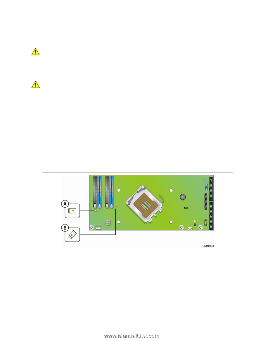
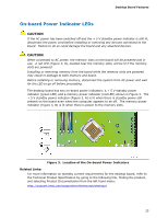
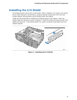
Desktop Board Features On-board Power Indicator LEDs CAUTION If the AC power has been switched off and the + 5 V standby power indicator is still lit, disconnect the power cord before installing or removing any devices connected to the board. Failure to do so could damage the board and any attached devices. CAUTION When connected to AC power, the memory slots on the board will be powered and in use. A red LED (Figure 3, B), located near the memory slots, will be lit if the memory slots are powered. Installing or removing memory from the board while the memory slots are powered may result in damage to both memory and board. Before installing or removing memory, disconnect the system from AC power and wait for the LED to go off before proceeding. The desktop board has two on-board power indicators: a + 5 V standby power indicator (green LED) and a memory power indicator (red LED) shown in Figure 3. The + 5 V standby power indicator (Figure 3, A) is lit when there is standby power still present on the board even when the computer appears to be off. The memory power indicator (Figure 3, B) is lit when there is power to the memory slots. Figure 3. Location of the On-board Power Indicators Related Links: For more information on standby current requirements for the desktop board, refer to the Technical Product Specification by going to the following link, finding the product, and selecting Product Documentation from the left-hand menu: http://support.intel.com/support/motherboards/desktop/ 25
-
 1
1 -
2
-
3
-
4
-
5
-
6
-
7
-
8
-
9
-
10
-
11
-
12
-
13
-
14
-
15
-
16
-
17
-
18
-
19
-
 20
20 -
 21
21 -
 22
22 -
 23
23 -
 24
24 -
 25
25 -
 26
26 -
 27
27 -
 28
28 -
 29
29 -
 30
30 -
31
-
32
-
33
-
34
-
35
-
36
-
37
-
38
-
39
-
40
-
41
-
42
-
43
-
44
-
45
-
46
-
47
-
48
-
49
-
50
-
51
-
52
-
53
-
54
-
55
-
56
-
57
-
58
-
59
-
60
-
61
-
62
-
63
-
64
-
65
-
66
-
67
-
68
-
69
-
70
-
71
-
72
-
73
-
74
-
75
-
76
-
77
-
78
-
79
-
80
-
81
-
82
-
83
-
84
 |
 |