Intel DQ965CO English Product Guide - Page 51
Connecting to the Parallel Port Header, Table 11. Parallel Port Header Signal Names
 |
View all Intel DQ965CO manuals
Add to My Manuals
Save this manual to your list of manuals |
Page 51 highlights
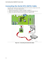
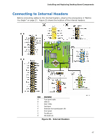
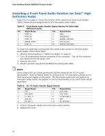
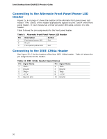
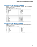
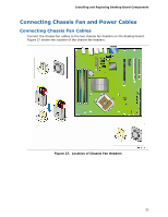
Installing and Replacing Desktop Board Components Connecting to the Parallel Port Header See Figure 25, G for the location of the parallel port header. Table 10 shows the pin assignments for the header. Table 11. Parallel Port Header Signal Names Pin Signal Name Pin Signal Name 1 STROBE# 3 PD0 5 PD1 2 AUTOFD# 4 FAULT# 6 INIT# 7 PD2 8 SLCTIN# 9 PD3 11 PD4 13 PD5 10 Ground 12 Ground 14 Ground 15 PD6 16 Ground 17 PD7 18 Ground 19 ACK# 21 BUSY 23 PERROR 20 Ground 22 Ground 24 Ground 25 SELECT 26 Key (no pin) Connecting to the Serial Port Header See Figure 25, D for the location of the serial port header. Table 10 shows the pin assignments for the header. Table 12. Serial Port Header Signal Names Pin Signal Name 1 DCD Pin Signal Name 2 RXD# 3 TXD# 5 Ground 7 RTS 4 DTR 6 DSR 8 CTS 9 RI 10 No connection 51
-
 1
1 -
2
-
3
-
4
-
5
-
6
-
7
-
8
-
9
-
10
-
11
-
12
-
13
-
14
-
15
-
16
-
17
-
18
-
19
-
20
-
21
-
22
-
23
-
24
-
25
-
26
-
27
-
28
-
29
-
30
-
31
-
32
-
33
-
34
-
35
-
36
-
37
-
38
-
39
-
40
-
41
-
42
-
43
-
44
-
45
-
 46
46 -
 47
47 -
 48
48 -
 49
49 -
 50
50 -
 51
51 -
 52
52 -
 53
53 -
 54
54 -
 55
55 -
 56
56 -
57
-
58
-
59
-
60
-
61
-
62
-
63
-
64
-
65
-
66
-
67
-
68
-
69
-
70
-
71
-
72
-
73
-
74
-
75
-
76
-
77
-
78
-
79
-
80
-
81
-
82
-
83
-
84
 |
 |