Intel DQ965CO English Product Guide - Page 7
SATA Port Mapping for Desktop Board DQ965CO After RAID is Enabled - i o shield
 |
View all Intel DQ965CO manuals
Add to My Manuals
Save this manual to your list of manuals |
Page 7 highlights
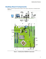
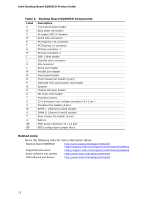
Contents A Error Messages and Indicators BIOS Beep Codes 73 BIOS Error Messages 73 B Regulatory Compliance Safety Regulations 75 Place Battery Marking 75 European Union Declaration of Conformity Statement 76 Product Ecology Statements 77 Lead-Free Desktop Board 80 EMC Regulations 81 Ensure Electromagnetic Compatibility (EMC) Compliance 82 Product Certifications 83 Board-Level Certification Markings 83 Chassis and Component Certifications 84 Figures 1. Desktop Board DQ965CO Components 11 2. LAN Connector LEDs 18 3. Location of the On-board Power Indicators 25 4. Installing the I/O Shield 29 5. Desktop Board DQ965CO Mounting Screw Hole Locations 31 6. Lift Socket Lever 32 7. Lift the Load Plate 32 8. Remove the Protective Socket Cover 33 9. Remove the Processor from the Protective Processor Cover 33 10. Install the Processor 34 11. Close the Load Plate 34 12. Position the Thermal Module Over the Mounting Holes 35 13. Use Care Routing the Thermal Module Fan Cable 36 14. Secure the Thermal Module 36 15. Connect the Thermal Module Fan Cable 37 16. Dual Channel Memory Configuration Example 1 38 17. Dual Channel Memory Configuration Example 2 39 18. Dual Channel Memory Configuration Example 3 39 19. Use DDR2 DIMMs 40 20. Installing a DIMM 41 21. Installing a PCI Express x16 Card 43 22. Removing a PCI Express x16 Card 44 23. Connecting the IDE Cable 45 24. Connecting the Serial ATA Cable 46 25. Internal Headers 47 26. Back Panel Audio Connectors 52 27. Location of Chassis Fan Headers 53 28. Connecting Power Supply Cables 54 29. Location of Other Connectors and Headers 55 30. Location of the BIOS Configuration Jumper Block 56 31. Back Panel Connectors 59 32. Removing the Battery 64 33. Original SATA Port Mapping for Desktop Board DQ965CO 69 34. SATA Port Mapping for Desktop Board DQ965CO After RAID is Enabled 70 vii
-
 1
1 -
 2
2 -
 3
3 -
 4
4 -
 5
5 -
 6
6 -
 7
7 -
 8
8 -
 9
9 -
 10
10 -
 11
11 -
 12
12 -
13
-
14
-
15
-
16
-
17
-
18
-
19
-
20
-
21
-
22
-
23
-
24
-
25
-
26
-
27
-
28
-
29
-
30
-
31
-
32
-
33
-
34
-
35
-
36
-
37
-
38
-
39
-
40
-
41
-
42
-
43
-
44
-
45
-
46
-
47
-
48
-
49
-
50
-
51
-
52
-
53
-
54
-
55
-
56
-
57
-
58
-
59
-
60
-
61
-
62
-
63
-
64
-
65
-
66
-
67
-
68
-
69
-
70
-
71
-
72
-
73
-
74
-
75
-
76
-
77
-
78
-
79
-
80
-
81
-
82
-
83
-
84
 |
 |
