Intel DX58SO2 English Product Guide - Page 13
Table 2. Intel Desktop Board DX58SO2 Components, Desktop Board Features, Label, Description - front side bus
 |
View all Intel DX58SO2 manuals
Add to My Manuals
Save this manual to your list of manuals |
Page 13 highlights
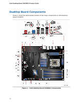
Desktop Board Features Table 2. Intel Desktop Board DX58SO2 Components Label Description A Front panel audio header B PCI Express 1.1 x1 connector C S/PDIF header D PCI Express 2.0 x16 connector (x8 electrical) E PCI bus connector F PCI Express 2.0 x16 connector G PCI Express 1.1 x1 connector H PCI Express 2.0 x16 connector I Rear chassis fan header J Back panel connectors K Processor fan header L 12 V processor core voltage connector (2 x 4 pin) M Processor socket N DIMM 4 socket O DIMM 1 socket P DIMM 5 socket Q DIMM 2 socket R DIMM 6 socket S DIMM 3 socket T Main power connector (2 x 12 pin) U Front chassis fan header V ICH10R W Serial ATA connectors (3 Gb/s) X Serial ATA connectors (6 Gb/s) Y Chassis intrusion header Z Speaker AA USB 2.0 headers BB Front panel CIR receiver (input) header CC Back panel CIR transmitter (output) header DD BIOS configuration jumper block EE Front panel header FF Alternate front panel power LED header GG POST code LED display HH IEEE 1394a header II Battery JJ Reset button KK Power button LL Base clock frequency decrease button MM Base clock frequency increase button NN Auxiliary chassis fan header OO Diagnostic/status LEDs 13
-
 1
1 -
2
-
3
-
4
-
5
-
6
-
7
-
 8
8 -
 9
9 -
 10
10 -
 11
11 -
 12
12 -
 13
13 -
 14
14 -
 15
15 -
 16
16 -
 17
17 -
 18
18 -
19
-
20
-
21
-
22
-
23
-
24
-
25
-
26
-
27
-
28
-
29
-
30
-
31
-
32
-
33
-
34
-
35
-
36
-
37
-
38
-
39
-
40
-
41
-
42
-
43
-
44
-
45
-
46
-
47
-
48
-
49
-
50
-
51
-
52
-
53
-
54
-
55
-
56
-
57
-
58
-
59
-
60
-
61
-
62
-
63
-
64
-
65
-
66
-
67
-
68
-
69
-
70
-
71
-
72
-
73
-
74
-
75
-
76
-
77
-
78
-
79
-
80
-
81
-
82
-
83
-
84
-
85
-
86
-
87
-
88
-
89
-
90
 |
 |