Intel DX58SO2 English Product Guide - Page 8
Tables, Intel Desktop Board DX58SO2 China RoHS Material Self Declaration Table - block
 |
View all Intel DX58SO2 manuals
Add to My Manuals
Save this manual to your list of manuals |
Page 8 highlights
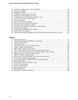
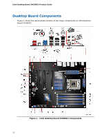
Intel Desktop Board DX58SO2 Product Guide 16. Example Configuration Using Six DIMMs 40 17. Use DDR3 DIMMs 41 18. Installing a DIMM 42 19. Installing a PCI Express x16 Card 44 20. Removing a PCI Express x16 Card 45 21. Installing Linked PCI Express Graphics Cards 46 22. Connecting the Serial ATA Cables 47 23. Internal Headers 48 24. Back Panel Audio Connectors 53 25. Location of the Chassis Fan Headers 54 26. Connecting Power Supply Cables 55 27. Location of the BIOS Configuration Jumper Block 56 28. Removing the Battery 62 29. Installing the WiFi/Bluetooth Module 64 30. POST Code LED Display 75 31. Intel Desktop Board DX58SO2 China RoHS Material Self Declaration Table............84 Tables 1. Feature Summary 9 2. Intel Desktop Board DX58SO2 Components 13 3. LAN Connector LEDs 18 4. Diagnostic LEDs 28 5. Front Panel Audio Header Signal Names 49 6. S/PDIF Header Signal Names 49 7. IEEE 1394a Header Signal Names 49 8. Front Panel CIR Receiver (Input) Header Signal Names 50 9. Back Panel CIR Header Emitter (Output) Header Signal Names 50 10. Chassis Intrusion Header Signal Names 51 11. USB 2.0 Header Signal Names 51 12. Alternate Front Panel Power LED Header Signal Names 52 13. Front Panel Header Signal Names 52 14. Jumper Settings for the BIOS Setup Program Modes 57 15. BIOS Beep Codes 73 16. Front-panel Power LED Blink Codes 73 17. BIOS Error Messages 74 18. Port 80h POST Codes 76 19. Safety Standards 79 20. EMC Regulations 85 21. Regulatory Compliance Marks 88 viii
-
 1
1 -
2
-
 3
3 -
 4
4 -
 5
5 -
 6
6 -
 7
7 -
 8
8 -
 9
9 -
 10
10 -
 11
11 -
 12
12 -
 13
13 -
14
-
15
-
16
-
17
-
18
-
19
-
20
-
21
-
22
-
23
-
24
-
25
-
26
-
27
-
28
-
29
-
30
-
31
-
32
-
33
-
34
-
35
-
36
-
37
-
38
-
39
-
40
-
41
-
42
-
43
-
44
-
45
-
46
-
47
-
48
-
49
-
50
-
51
-
52
-
53
-
54
-
55
-
56
-
57
-
58
-
59
-
60
-
61
-
62
-
63
-
64
-
65
-
66
-
67
-
68
-
69
-
70
-
71
-
72
-
73
-
74
-
75
-
76
-
77
-
78
-
79
-
80
-
81
-
82
-
83
-
84
-
85
-
86
-
87
-
88
-
89
-
90
 |
 |