Intel DX58SO2 English Product Guide - Page 7
Connecting the Processor Fan Heat Sink Cable to the Processor Fan Header - drivers
 |
View all Intel DX58SO2 manuals
Add to My Manuals
Save this manual to your list of manuals |
Page 7 highlights
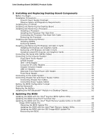
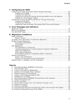
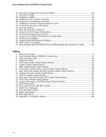
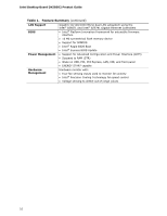
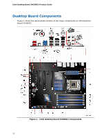
Contents 4 Configuring for RAID Configuring for RAID Using Intel® Matrix Storage Technology 69 Configuring the BIOS 69 Creating Your RAID Set 69 Loading the Intel Matrix Storage Technology RAID Drivers and Software 70 Setting Up a "RAID Ready" System 70 Configuring for External RAID Using Marvell* Storage Technology 71 Configuring the BIOS 71 Creating Your RAID Set 71 Loading the Marvell Storage Technology RAID Drivers and Software 71 A Error Messages and Indicators BIOS Error Codes 73 BIOS Error Messages 74 Port 80h POST Codes 75 B Regulatory Compliance Safety Standards 79 Battery Caution 79 European Union Declaration of Conformity Statement 80 Product Ecology Statements 81 Recycling Considerations 81 China RoHS 84 EMC Regulations 85 FCC Declaration of Conformity 85 Canadian Department of Communications Compliance Statement 86 Japan VCCI Statement 86 Korea Class B Statement 87 Ensure Electromagnetic Compatibility (EMC) Compliance 87 Product Certifications 88 Board-Level Certifications 88 Chassis- and Component-Level Certifications 89 ENERGY STAR*, e-Standby, and ErP Compliance 89 Figures 1. Intel Desktop Board DX58SO2 Components 12 2. LAN Connector LEDs 17 3. Location of the Back to BIOS Button 20 4. Location of the Standby Power Indicator 24 5. Onboard System Control Switches 25 6. Location of the Diagnostic/Status LEDs 27 7. Installing the I/O Shield 33 8. Intel Desktop Board DX58SO2 Mounting Screw Hole Locations 34 9. Unlatch the Socket Lever 35 10. Lift the Load Plate 36 11. Remove the Processor from the Protective Processor Cover 37 12. Install the Processor 37 13. Close the Load Plate 38 14. Connecting the Processor Fan Heat Sink Cable to the Processor Fan Header ..........39 15. Example Configuration Using Three DIMMs 40 vii
-
 1
1 -
 2
2 -
 3
3 -
 4
4 -
 5
5 -
 6
6 -
 7
7 -
 8
8 -
 9
9 -
 10
10 -
 11
11 -
 12
12 -
13
-
14
-
15
-
16
-
17
-
18
-
19
-
20
-
21
-
22
-
23
-
24
-
25
-
26
-
27
-
28
-
29
-
30
-
31
-
32
-
33
-
34
-
35
-
36
-
37
-
38
-
39
-
40
-
41
-
42
-
43
-
44
-
45
-
46
-
47
-
48
-
49
-
50
-
51
-
52
-
53
-
54
-
55
-
56
-
57
-
58
-
59
-
60
-
61
-
62
-
63
-
64
-
65
-
66
-
67
-
68
-
69
-
70
-
71
-
72
-
73
-
74
-
75
-
76
-
77
-
78
-
79
-
80
-
81
-
82
-
83
-
84
-
85
-
86
-
87
-
88
-
89
-
90
 |
 |