Intel DX58SO2 English Product Guide - Page 52
Alternate Front Panel Power LED Header, Front Panel Header
 |
View all Intel DX58SO2 manuals
Add to My Manuals
Save this manual to your list of manuals |
Page 52 highlights
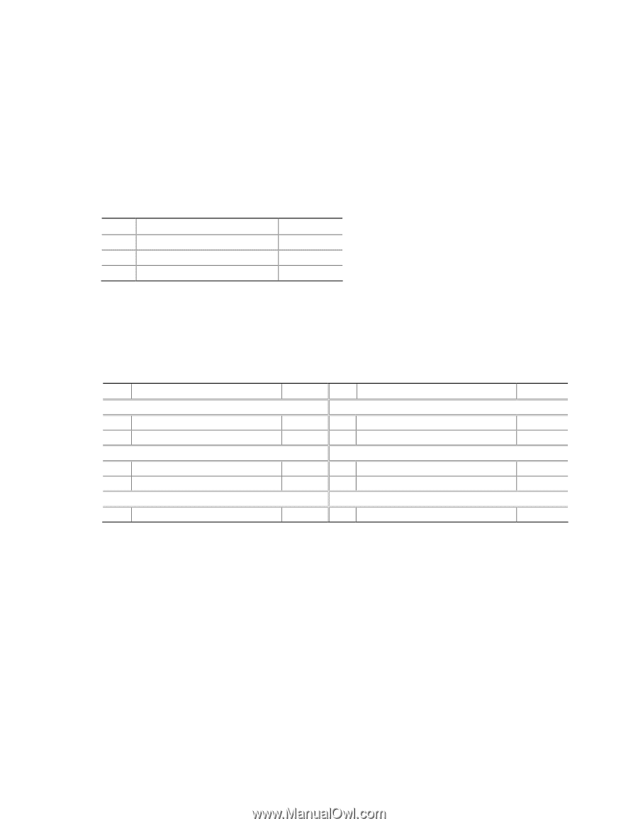
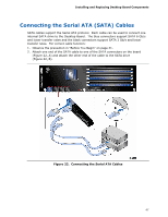
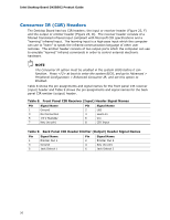
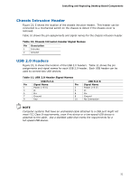
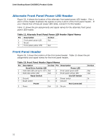
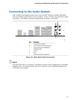
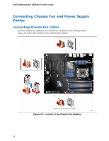
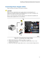
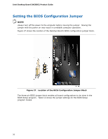
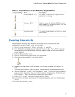
Intel Desktop Board DX58SO2 Product Guide Alternate Front Panel Power LED Header Figure 23, H shows the location of the alternate front panel power LED header. Pins 1 and 3 of this header duplicate the signals on pins 2 and 4 of the front panel header. If your chassis has a three-pin power LED cable, connect it to this header. Table 12 shows the pin assignments and signal names for the alternate front panel power LED header. Table 12. Alternate Front Panel Power LED Header Signal Names Pin Description 1 Front panel green LED 2 No pin 3 Front panel yellow LED In/Out Out Out Front Panel Header Figure 23, I shows the location of the front panel header. Table 13 shows the pin assignments and signal names for the front panel header. Table 13. Front Panel Header Signal Names Pin Description In/Out Pin Description Hard Drive Activity LED Power LED 1 Hard disk LED pull-up to +5 V Out 2 Front panel green LED 3 Hard disk active LED Out 4 Front panel yellow LED Reset Switch On/Off Switch 5 Ground 6 Power switch 7 Reset switch In 8 Ground Power Not Connected 9 Power Out 10 No pin In/Out Out Out In 52
-
 1
1 -
2
-
3
-
4
-
5
-
6
-
7
-
8
-
9
-
10
-
11
-
12
-
13
-
14
-
15
-
16
-
17
-
18
-
19
-
20
-
21
-
22
-
23
-
24
-
25
-
26
-
27
-
28
-
29
-
30
-
31
-
32
-
33
-
34
-
35
-
36
-
37
-
38
-
39
-
40
-
41
-
42
-
43
-
44
-
45
-
46
-
 47
47 -
 48
48 -
 49
49 -
 50
50 -
 51
51 -
 52
52 -
 53
53 -
 54
54 -
 55
55 -
 56
56 -
 57
57 -
58
-
59
-
60
-
61
-
62
-
63
-
64
-
65
-
66
-
67
-
68
-
69
-
70
-
71
-
72
-
73
-
74
-
75
-
76
-
77
-
78
-
79
-
80
-
81
-
82
-
83
-
84
-
85
-
86
-
87
-
88
-
89
-
90
 |
 |