Intel E7500 Design Guide - Page 19
Angle Attach Methodology Top View, Angle Attach Heatsink Modifications
 |
View all Intel E7500 manuals
Add to My Manuals
Save this manual to your list of manuals |
Page 19 highlights
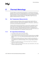
R Figure 5. 0° Angle Attach Methodology (Top View) Thermocouple Wire Thermal Metrology Die Substrate NOTE: Not to scale. Figure 6. 0° Angle Attach Heatsink Modifications Cement + Thermocouple Bead angle_attach_1 1.3 mm (0.05 in.) (0.5 mm (0.02 in.) Depth) NOTE: Not to scale. 3.3 mm (0.13 in.) Diameter (1.5 mm (0.06 in.) Depth) Angle_Attach_Heatsink_Mod Intel® E7500 MCH Thermal and Mechanical Design Guidelines 19
-
 1
1 -
2
-
3
-
4
-
5
-
6
-
7
-
8
-
9
-
10
-
11
-
12
-
13
-
 14
14 -
 15
15 -
 16
16 -
 17
17 -
 18
18 -
 19
19 -
 20
20 -
 21
21 -
 22
22 -
 23
23 -
 24
24 -
25
-
26
-
27
-
28
-
29
-
30
-
31
-
32
-
33
-
34
-
35
 |
 |

Thermal Metrology
R
Intel
®
E7500 MCH Thermal and Mechanical Design Guidelines
19
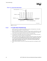
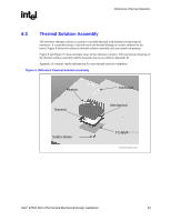
Figure 5. 0° Angle Attach Methodology (Top View)
Cement +
Thermocouple Bead
angle_attach_1
Thermocouple Wire
Die
Substrate
NOTE:
Not to scale.
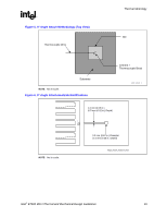
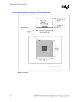
Figure 6. 0° Angle Attach Heatsink Modifications
Angle_Attach_Heatsink_Mod
1.3 mm (0.05 in.)
(0.5 mm (0.02 in.) Depth)
3.3 mm (0.13 in.) Diameter
(1.5 mm (0.06 in.) Depth)
NOTE:
Not to scale.