R
Intel
®
E7500 MCH Thermal and Mechanical Design Guidelines
3
Contents
1
Introduction
..........................................................................................................................
7
1.1
Design Flow
............................................................................................................
8
1.2
Definition of Terms
..................................................................................................
9
1.3
Reference Documents
..........................................................................................
10
2
Packaging Technology
......................................................................................................
11
3
Thermal Simulation
............................................................................................................
13
4
Thermal Specifications
......................................................................................................
15
4.1
Power
....................................................................................................................
15
4.2
Die Temperature
...................................................................................................
15
5
Thermal Metrology
.............................................................................................................
17
5.1
Die Temperature Measurements
..........................................................................
17
5.1.1
90° Angle Attach Methodology
..............................................................
17
5.1.2
0° Angle Attach Methodology
................................................................
18
5.2
Power Simulation Software
...................................................................................
20
6
Reference Thermal Solutions
............................................................................................
21
6.1
Operating Environment
.........................................................................................
21
6.2
Mechanical Design Envelope
................................................................................
21
6.3
Thermal Solution Assembly
..................................................................................
23
6.3.1
Heatsink Orientations
............................................................................
25
6.3.2
Extruded Heatsink Profiles
....................................................................
26
6.3.3
Mechanical Interface Material
...............................................................
27
6.3.4
Thermal Interface Material
....................................................................
27
6.3.5
Heatsink Clip
.........................................................................................
27
6.3.6
Clip Retention Anchors
..........................................................................
28
6.3.7
Board Level Component Keep-out Dimensions
....................................
28
6.4
Reliability Requirements
.......................................................................................
30
Appendix A:
Thermal Solution Component Suppliers
............................................................................
31
Appendix B:
Mechanical Drawings
.........................................................................................................
33
 1
1 2
2 3
3 4
4 5
5 6
6 7
7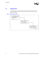 8
8 9
9