Intel E7500 Design Guide - Page 21
Reference Thermal Solutions - motherboard
 |
View all Intel E7500 manuals
Add to My Manuals
Save this manual to your list of manuals |
Page 21 highlights
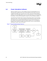
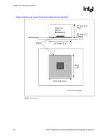
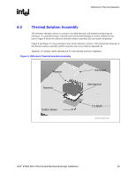
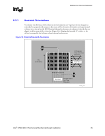
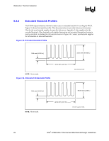
Reference Thermal Solutions R 6 6.1 6.2 Reference Thermal Solutions Intel has developed a reference thermal solution designed to meet the cooling needs of the MCH at worst-case conditions. This chapter describes the overall requirements for the reference thermal solution, including critical-to-function dimensions, operating environment, and validation criteria. Other chipset components may or may not need thermal solutions, depending on specific system local-ambient operating conditions. For information on the P64H2 thermal solutions, refer to the Intel® 82870P2 PCI/PCI-X 64-bit Hub 2 (P64H2) Thermal and Mechanical Design Guidelines. Operating Environment The reference thermal solution was designed assuming a maximum local-ambient temperature of 50 C. The minimum recommended airflow velocity at the heatsink is 200 lfm (linear feet per minute). The approaching airflow temperature is assumed to be equal to the local-ambient temperature. The thermal designer must carefully select the location to measure airflow to obtain an accurate estimate. These local-ambient conditions are based on a 35 C external-ambient temperature at sea level. (External-ambient refers to the environment external to the system.) Mechanical Design Envelope Though each design may have unique mechanical volume and height restrictions or implementation requirements, the height, width, and depth constraints typically placed on the E7500 MCH thermal solution is shown in Figure 8. When using heatsinks that extend beyond the MCH reference heatsink envelope shown in Figure 8, any motherboard components placed between the heatsink and motherboard cannot exceed 2.286 mm (0.090 in.) in height. Intel® E7500 MCH Thermal and Mechanical Design Guidelines 21
-
 1
1 -
2
-
3
-
4
-
5
-
6
-
7
-
8
-
9
-
10
-
11
-
12
-
13
-
14
-
15
-
 16
16 -
 17
17 -
 18
18 -
 19
19 -
 20
20 -
 21
21 -
 22
22 -
 23
23 -
 24
24 -
 25
25 -
 26
26 -
27
-
28
-
29
-
30
-
31
-
32
-
33
-
34
-
35
 |
 |